Alesis QuadraVerb Service Manual------
6
08/13/04
Signal
Pin
Function
RAS
3
- DRAM Row Address Strobe
CAS
4
- DRAM Column Address Strobe
MDE
5
-DRAM output enable.
STB
40
- Instructs DASP 24 to accept 8031 DATA
CLK
42
- 24MHz clock from Z1
RST
53 -
RESET
INH
54
- Controls sample and hold circuit timing.
SNHOUT
0
55
"
SNHOUT
1
56
"
LSTMSB
57
- This signal indicates the last state of the MSB (the sign bit in two's complement math). This
signal, in conjunction with R36, R47, R48, and C13, is used to bias the incoming analog signal slightly positive, or
negative, depending on the result of the last DAC cycle (i.e. if the last DAC cycle started off with a negative value,
LSTMSB will be 1, causing the input to the sample and hold circuit to pull slightly positive. On the next cycle, the reverse
will occur). This reduces any audio pop during the attack portion of the input signal, and allows for a faster response to
small signals.
ADC
74
- A/D comparison input.
OVFLO
75
- This signal indicates a math overflow condition, and consequently turns on the clip LED circuit.
WR
84
- DRAM write enable
5.0 Test Procedures
If possible, user data should be saved (a DataDisk is recommended) prior to any servicing.
This, of course, may not always be possible (i.e. dead power supply, bad reset signal, corrupt data,
etc.). Saving user data may also be accomplished after unit functionality is restored (i.e. power
supply, or reset line, is repaired), and prior to further servicing, and testing. The unit should always
be reinitialized (power unit up while holding "BYPASS" and "PROG" buttons down) after changing
the EPROM, SRAM, or any part of the battery backup. To perform the QuadraVerb's self diagnostics
connect a MIDI cable between MIDI in, and MIDI out. Power up the unit while holding the "BYPASS",
and "CONFIG", buttons down. The unit will then test ROM, RAM, Button LEDs, MIDI, and the clip
LED. In the event of a ROM, RAM, or MIDI failure, the unit will stop, and the display will show
"ERROR IN {COMPONENT}".
6.0 Adjustments
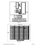
There are no adjustments necessary, unless a DAC adjust trimpot has been installed at the
time of service. The easiest way to adjust the DAC is to use a fast lezlie program, with no signal
input. With the lezlie output turned fully up, adjust the trimpot for a minimum noise floor. (See section
7.0 for installation instructions.)
7.0 Updates and Revisions
Note that these items may not apply to all board revisions. Where updates are board revision
specific, the
bold
type characters at the beginning of the note indicates applicable board revision
designations.
7.1 D15
A-E
Zener diode (D15) at bottom, right-hand corner of board (in reset circuit) should be a
metal zener and NOT a glass zener. The glass types have been found to be somewhat unreliable.
Summary of Contents for QUADRAVERB
Page 16: ...Diagram 7 Alesis QuadraVerb Service Manual 10 08 13 04 ...
Page 17: ...Diagram 8 Diagram 9 Alesis QuadraVerb Service Manual 11 08 13 04 ...
Page 20: ...9 0 Schematics Alesis QuadraVerb Service Manual 14 08 13 04 ...
Page 21: ...Alesis QuadraVerb Service Manual 15 08 13 04 ...
Page 46: ...NOTES Alesis QuadraVerb Service Manual 40 08 13 04 ...


