


Local testing and operating sequence
Tests and Measurements
............................................................................................................................................................................................................................................................
PN 8DG08136CAAA
Issue 1 March 2008
3-23
............................................................................................................................................................................................................................................................
........................................................................................................................................................................................................................
4
Cross-connect the VC4-7V to one port of the 10 x 1 GbE PIM (PIM1GE), as shown in
Chapter 4
,
“Cross-connection between a local and a remote data port” (p. 4-12)
.
........................................................................................................................................................................................................................
5
Start transmitting at 100% of the available bandwidth
........................................................................................................................................................................................................................
6
Check that all the frames received are the same of those transmitted and no alarms are
detected by the instrument for 5 minutes.
........................................................................................................................................................................................................................
7
Alarms detection — Perform the cross-connection described above.
•
From EML-USM -> Select “Equipment” -> “Data board Navigation,” then insert login
and password. The Data CT starts.
–
In the “1850TSS User Service Management..” window, double-click on the board
(i.e., r1sr1/board#2). The local and remote Data ports are displayed.
–
Select a local port. From the pop-up menu (click on the right button of the mouse),
select “Configure Ethernet port.”
–
In “Ethernet port Configuration” window, select “Configuration” tag and set “Up”
in “Admin. Status” field. Click on “OK.”
–
Select the port again. From the pop-up menu (click on the right button of the
mouse), select “Ethernet Port Properties.” Open the “Alarms” tag and check the
presence of the LOS alarm (red square).
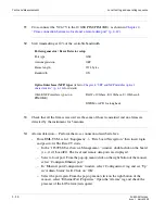
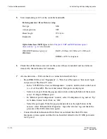
Pattern generator / Error Detector setup
Port type
GbE
Auto-negotiation
ON
Frame length
1518 bytes
Bandwidth
100%
Optical interfaces (SFP) types
(refer to
Chapter 4
,
“SFP and XFP modules optical
characteristics” (p. 4-16)
for details)
GbE SFP interface types (on PIM1GE)
B&W = 1000 Base SX / 1000 Base LX / 1000 Base
ZX
CWDM = APD (C8L1-1D2) for long haul,
PIN (C8S1-1D2) for short haul
Summary of Contents for 1850 TSS-320
Page 6: ... List of figures v i PN 8DG08136CAAA Issue 1 March 2008 ...
Page 8: ... List of tables v i i i PN 8DG08136CAAA Issue 1 March 2008 ...
Page 16: ... Safety rules Safety 1 4 PN 8DG08136CAAA Issue 1 March 2008 ...
Page 138: ... Other technical support services Technical Support A 14 PN 8DG08136CAAA Issue 1 March 2008 ...
Page 140: ... Glossary GL 2 PN 8DG08136CAAA Issue 1 March 2008 ...