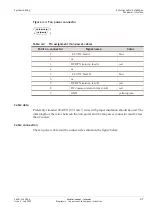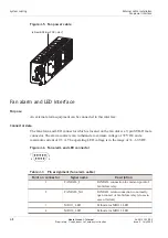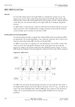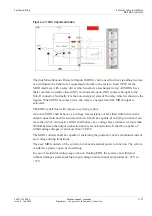
Cable connection
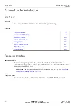
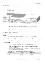
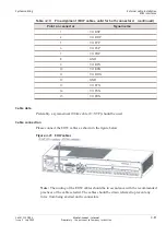
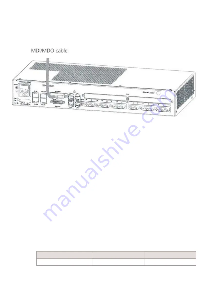
Please connect the MDI/MDO cable as shown in the figure below:
ote:
The routing of the MDI/MDO cable should be in accordance with the
recommended practices of the cable selected. The cable should be strain relieved to
prevent any force from being exerted on the connectors.
Synchronization interface
Purpose
The synchronization interface provides input and output connection points for
synchronization purposes. The signal format is the G.703-13a compliant 2048 kHz signal
. The user can select the impedance of the interfaces (75 Ω coaxial or 120 Ω symmetrical)
by wiring the cable appropriately and setting the impedance from CIT.
System clock input
•
The system is equipped with one single Station Clock Input process. The station clock
input operates with a 2 MHz clock signal according to ITU-T Rec. G.703.10.
•
The system limits the acceptable types of Station Clock Input signal to 2MHz
(G.703.10) signal only.
•
The station clock input at the customer connection point meets the requirements for
return loss based on the following table:
Table 4-5
Return loss of 30 channel market station clock inputs
Input type
Frequency
Return loss
2 MHz
2048 kHz
15 dB
Figure 4-12 MDI/MDO cable
System cabling
External cable installation
MDI/MDO interface
...................................................................................................................................................................................................................................
...................................................................................................................................................................................................................................
4-14
Alcatel-Lucent – Internal
Proprietary – Use pursuant to Company instruction
365-313-103R8.0
Issue 2
July 2009


