


...................................................................................................................................................................................................
5
Set the PDH analyzer to 2 Mbit/s, 2
15
-1 PRBS pattern. Connect the PDH analyzer to
TP1.1. Start a BER test.
...................................................................................................................................................................................................
6
Display the raised alarm list on the ITM-CIT, and verify that the requirements mentioned
in the table below are met.
Result:
Requirements
PDH analyzer:
o errors
Alarms reported on the ITM-CIT:
“STM*cES”, STM* ot Expected Input
Signal
...................................................................................................................................................................................................
7
Check if the slot and port number of the ES alarm source corresponds with the physical
position on the ODF to which the optical loop is connected.
...................................................................................................................................................................................................
8
Set the Line Ports to “
Monitored
”.
...................................................................................................................................................................................................
9
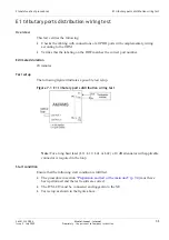
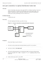
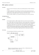
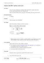
Connect the optical power meter to the fiber returning from the ODF (LP1.1 input) (refer
to
Figure 7-2, “Line port connection to optical distribution frame test” (p. 7-8)
...................................................................................................................................................................................................
10
Measure the optical transmit power level.
...................................................................................................................................................................................................
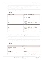
11
Verify that the requirements mentioned in the table below are met.
Result:
Power ranges:
Interface
Wavelength [nm]
Power range [dBm]
S1.1
1310
–15 ... –8
S4.1
1310
–15 ... –8
L1.1
1310
–5 ... 0
L1.2
1550
–5 ... 0
L4.1
1310
–3 ... +2
L4.2
1550
–3 ... +2
ote:
Subtract 0.50 dB per optical connection (for the suggested set-up 1.5 dB (3
connections)) and subtract 0.2 dB per fiber segment (0.4 dB for 2 fiber segments).
Stand-alone test procedures
Line port connection to optical distribution frame test
...................................................................................................................................................................................................................................
...................................................................................................................................................................................................................................
365-313-103R8.0
Issue 2
July 2009
Alcatel-Lucent – Internal
Proprietary – Use pursuant to Company instruction
7-9