


— 23 —
— 22 —
GETTING STARTED
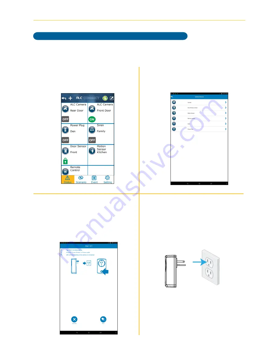
Pairing the Power Switch
v
Tap
Power Plug
.
u
At the Status screen, tap
+
.
x
Plug the Power Switch into a standard
AC outlet having 120V, 60Hz; the LED
will blink indicating the Power Switch
is in the pairing mode.
w
Tap
Pair
to start the Pairing process.
Follow the on screen instructions.
Model AHS613 does not include an Power Switch.


