background image

 40 


system reset........................................24 
system test............................................7 
temperature ..............................5, 18, 19 
temperature type C/F..........................19 
test initialization message ..................16 
test initialization screen......................14 
test leads.............................................14 
test modes ............................................4 

multimeter ........................................4 

specific gravity ................................ 5 
temperature ...................................... 5 
voltmeter.......................................... 4 

test parameters ................................... 20 
test parameters menu ......................... 20 
upload readings.............................. 6, 19 
voltmeter........................................ 4, 17 
voltmeter screen ................................ 17 
warning messages.............................. 22 


Summary of Contents for Cellcorder

Page 1: ...Cellcorder Instruction Manual Revision 5 0 990 South Rogers Circle Suite 11 Boca Raton FL 33487 Tel 561 997 2299 Fax 561 997 5588 http www alber com...

Page 2: ...used in conjunction with this software product Without prejudice to the foregoing generality Alb rcorp shall not be liable for the loss or corruption of data or programs stored in or used in conjunct...

Page 3: ...pyright and trademark notices restricted rights legends and other proprietary markings RESTRICTIONS You may not sublicense rent or lease the Alb rcorp Software You may not reverse engineer decompile d...

Page 4: ...are is classified as Commercial Computer Software and the Government is acquiring only restricted rights in the software and its documentation as that term is defined in Clause 252 227 7013 c 1 of the...

Page 5: ...nsure equipment is provided adequate ventilation Do not block equipment ventilation openings Do not exceed equipment voltage or power ratings and capabilities Make sure that equipment is properly grou...

Page 6: ...Cellcorder Initial System Test 7 3 OPERATING INSTRUCTIONS 10 3 1 General Concepts 10 3 2 Before Using the Cellcorder 11 3 3 General Operating Notes 11 3 4 Operation Notes 12 3 4 1 Multimeter Mode 13 3...

Page 7: ...ring the Calibration Screen 28 3 8 2 Entering the Password 28 3 8 3 Recording the Before Calibration Readings 29 3 8 4 Calibrating the Cellcorder 31 3 8 5 Backing Up and Restoring the Calibration 35 4...

Page 8: ...cell voltage being tested and 2 the Cellcorder displays a Low Current Cell or Connect Problem error message Although this modification reduces the risk of damage to the Cellcorder remember to never le...

Page 9: ...or longer than 1 second before the test will begin WARNING The maximum voltage the Cellcorder can read is 16V Do not attempt to read Overall Volts Use a separate meter then enter the reading manually...

Page 10: ...cedure Overview The Cellcorder is a self contained battery powered unit comprised of a microprocessor load resistor display and rechargeable battery Two sets of test leads are provided a standard set...

Page 11: ...omatically indexes the display and memory storage to the next higher number This mode allows you to take valid recorded readings at a rate of ten to twelve per minute 1 3 2 Multimeter The Cellcorder i...

Page 12: ...voltage range covers all cells or modules up to 16 volts Reading accuracy is to four full digits 1 4 2 Internal Cell Resistance Internal resistance of a cell can be determined by how that cell respon...

Page 13: ...alyzed and displayed in an easy to read bar graph or tabulated format Refer to the Battery Analysis User s Guide 1 4 6 System Display The test sequence instructions and test results appear on a bright...

Page 14: ...will help protect the unit from minor bumps during daily use Verify that all contents are in the box and carrying case Each system should include the materials described in Cellcorder Parts List This...

Page 15: ...e the unit returns to the Diagnostics Menu A D Channel Alb rcorp recommends that you use this diagnostic only when instructed by Alb rcorp technical support This selection displays the reading from th...

Page 16: ...rough a series of transmit and receive signals and logs the errors on the display After the sequence is started the unit counts from 0 to 255 and continues cycling 0 to 255 until ESC is pressed If err...

Page 17: ...e Profile X Capacity Vented Cells Every 3 to 5 years until signs of degradation then once every year Capacity Sealed Cells Every year NOTE VRLA or sealed cells need to be tested more frequently becaus...

Page 18: ...test leads the battery charger module and the RS 232 cable Prior to testing charge the Cellcorder for at least eight hours to guarantee six hours of battery operation If the batteries wear down durin...

Page 19: ...warning message appears CAUTION Do not change memory configuration after data has been taken or the memory will be scrambled Changing back will unscramble the memory To continue press ENTER then sele...

Page 20: ...gs 3 4 1 Multimeter Mode When this mode is selected the screen prompts the user to specify how many intercell connection readings are to be taken Refer to Connecting the Test Leads and to Application...

Page 21: ...on Battery 1 cells 3 4 2 Connecting the Test Leads The connection of the test leads for any type of resistance measuring instrument is very important and is directly related to the accuracy of the rea...

Page 22: ...al posts have a layer of lead dioxide lead sulfate copper oxide or dirt mixed with No Ox grease All of these are high in resistance so make sure the test leads have good connection to the metal surfac...

Page 23: ...t to do If an error code is displayed refer to Error Codes and Warning Messages It is possible to find a cell that is failing so badly that the loaded voltage drops by more than 1 5 volts In this case...

Page 24: ...5 Voltmeter Mode To enter this mode select option 2 Voltmeter from the Mode Select Menu When this mode is entered the display indicates the present cell number to be tested and the Battery ID as show...

Page 25: ...s TEST a second time to store the new voltage reading Or press ESC to return to the previous screen displaying the data of the cell being reviewed 3 4 6 Entering Specific Gravity Temperature and Overa...

Page 26: ...eypad then press ENTER 3 4 6 5 Temperature Type Selection This selection can only be made when cell 001 is selected Refer to Cell Selection Press ENTER until the cursor is in the temperature type F or...

Page 27: ...n loaded When the display reaches 64 or 256 depending on the configuration selected all readings have been loaded Note that all uploaded temperature values are rounded off to the nearest whole number...

Page 28: ...0 minutes prior to using it plugged in to AC The life of the battery is directly related to how well it is charged Do not store the Cellcorder in a discharged condition Refer to Application Note CC 00...

Page 29: ...ilure Program RAM Failure Boot EPROM Failure NV PROM Failure PIO Failure A D Failure Data RAM Failure The following error messages may appear during a Multimeter Mode test ERROR CODE 1 Unit cannot loc...

Page 30: ...l possibly opened up at start of test ERROR CODE 9 VF VL 1 5V Failing cell Cell cannot maintain test current ERROR CODE A VF VL I is too large Instrument overflow The unit displays the message _ _ REA...

Page 31: ...ST BUTTON 1 SECOND TO RETRY The discharge warning message appears when the battery is fully discharged When a low battery is detected the unit displays this message once a minute for five minutes and...

Page 32: ...This test takes about ten seconds and cannot be interrupted Upon completion the unit returns to the Diagnostics Menu 3 6 3 A D Channel AD CHAN Alb rcorp recommends that you use this diagnostic only w...

Page 33: ...isplayed if the calibrated mode is selected 3 6 4 Relays WARNING If the Relays diagnostic is enabled while the Cellcorder is connected to a voltage source the Cellcorder can be permanently damaged Bef...

Page 34: ...changed An asterisk on the top right corner of a menu indicates the memory configuration is set to 7 x 256 No asterisk indicates a 28 x 64 configuration Erasing String Data After uploading Cellcorder...

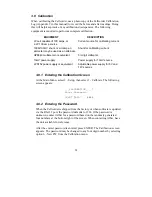
Page 35: ...source LPS152 power supply or equivalent Adjustable power supply for 6V and 12V sources 3 8 1 Entering the Calibration Screen At the Main Menu select 3 Setup then select 1 Calibrate The following scr...

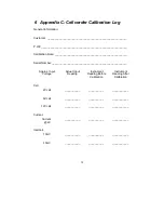
Page 36: ...2 Connect a 2V cell to the Cellcorder using the standard two lead voltage leads supplied with the Cellcorder 3 Measure the voltage using the HP 5 digit voltmeter or equiv 4 Record the value on the Cal...

Page 37: ...4 Connect the HP 5 digit voltmeter or equiv across the shunt 5 From the Calibration menu select option 4 Current 6 To start the test press TEST 7 Measure the current mV reading across the shunt using...

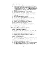
Page 38: ...oltage using the HP voltmeter 9 Record the value under Intercell 10mV Actual Input 10 Measure the voltage using the Cellcorder 11 Record the value under Intercell 10mV Before Calibration 3 8 4 Calibra...

Page 39: ...tion menu select option 2 6V Cell 3 Measure the voltage using the HP voltmeter 4 Press the UP and DOWN arrow keys until the reading on the Cellcorder matches the HP DMM reading 5 Select the Multimeter...

Page 40: ...med using a 2 volt source Do not attempt to perform this procedure with a 6 volt or 12 volt module The Cellcorder will report an error message and not allow calibration to continue 1 Using the multime...

Page 41: ...ot change by more than 30 V If the value is within this 30 V range go to step 5 4 If the reading changed more than 30 V then the offset adjustment on the input preamp must be adjusted Adjust RV3 until...

Page 42: ...ery has time to respond The battery charger should only require minor adjustments if the battery has been replaced otherwise no adjustment should be needed The life of the battery is directly related...

Page 43: ...RS 232 Cable _____ 1 Voltage Lead Cable Set 2 Leads _____ 1 Resistance Test Cable 3 Leads _____ 1 Cellcorder Operation Manual _____ 1 Battery Analysis Software BAS _____ 1 BAS Manual _____ 1 Carrying...

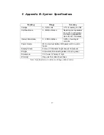
Page 44: ...te CC 001 for details Intercell Resistance 0 2 000 milliohms 0 25 of reading 2 microhm Power Source 8V 5 amp hour battery Will power unit for up to 6 hours Display Screen 4 Line x 20 character bright...

Page 45: ...Serial Number ___________________________________________________ Approx Input Actual Input Instrument Instrument Voltage Reading Reading Before Reading After Calibration Calibration Cell 2V cell ___...

Page 46: ...25 diagnostics menu 8 25 digital hydrometer 19 display diagnostic 8 25 erasing string data 27 error codes 22 float voltage readings 5 12 13 hydrometer 19 initial system test 7 intercell resistance 5...

Page 47: ...F 19 test initialization message 16 test initialization screen 14 test leads 14 test modes 4 multimeter 4 specific gravity 5 temperature 5 voltmeter 4 test parameters 20 test parameters menu 20 uploa...

Reviews: