7
Nov. 2006
MODEL 355 MECHANICAL INSTALLATION
Step 1
. Unpack crate and inventory parts, comparing against the packing list in the front of this manual,
to verify all parts are on site.
Step 2
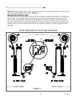
. Using a tape measure, determine the clear opening width. Compare this measurement with the
door ordered width. See crate label for door ordered dimensions.
NOTE
THE CLEAR OPENING WIDTH MUST BE THE SAME AS THE DOOR
MANUFACTURED WIDTH IN ORDER FOR THE RESET SYSTEM TO
FUNCTION PROPERLY. THIS MEANS THE DISTANCE BETWEEN
THE SIDE FRAMES AT THE TOP, MIDDLE AND BOTTOM MUST
EQUAL THE DOOR WIDTH.
Step 3
.Verify that the opening is
plumb and that the floor slab is
level. Shimming may be required
to level the side columns but no
more then ½”. Refer to approval
drawings for this door to confirm
drive side mounting (left or right-
hand).
Step 4
. Remove the side
columns from crate (one at a
time). Remove covers from both
side columns and set aside.
Remove springs and inner covers
from both side columns. Erect
both columns and place them in
position against the wall with
inner edges in line with the door
jambs. Verify the width per door
specification.
Step 5
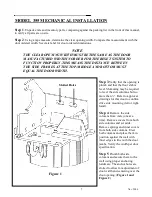
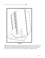
. Plumb both side
columns and secure them to the
wall using proper anchoring
hardware. The anchor holes are
slotted to allow for adjustment of
door width and centering over the
door opening. (Figure 1 and
Figure 2)
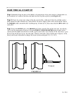
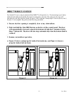
Slotted Holes
Figure 1
Summary of Contents for 350016-0000
Page 3: ......
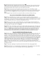
Page 12: ...12 Nov 2006 Figure 6 Figure 7 ...
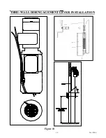
Page 14: ...14 Nov 2006 THRU WALL DISENGAGEMENT LEVER INSTALLATION Figure 10 ...
Page 20: ...20 Nov 2006 ...


