11
Nov. 2006
Step 11.
Slide the bottom rail profile into the base of the curtain and center. Once the bottom beam is
centered, then locate the 2 predrilled holes on each end of profile, drill through the fabric and use the
provided slotted screws and acorn nut to secure the bottom beam in place.
Step 12
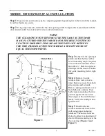
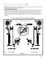
. Run the tensioning rope through the appropriate pulleys in the counterbalance system
corresponding to the drawing placed inside the side columns. Ensure the rope is run through the sliding
part of the CSE block. (Figure 4) Run the rope through the hole in the aluminum bracket on bottom
profile.
While running the rope for the door try to ensure that there are no twists or kinks in the rope.
DO NOT CUT EXCESS ROPE UNTIL STEP 15 HAS BEEN DONE.
Step 13
. Re-install both inner side column covers. Re-install counterbalance springs inside side
columns. Take note that the springs must be attached so that the spring is sitting against the short section
of brush that is on the inner cover. This brush dampens the movement of the spring allowing for a quiet
function. The spring will be noisy if this step is not performed correctly.
Step 14
. Using a come-a-long or similar pulling device, stretch the springs to the horizontal arrows
marked on the diagrams located on the side column covers. Remove slack from the tensioning rope and
secure rope in place by tying a knot in it (Figure 4).
Step 15
. When the counter balance system has been fully installed, disengage the drive unit brake and
manually move door over its entire range of motion. Ensure that the fabric and windclips go behind the
inner cover. NOTE: The door must be cycled 20-30 times to allow for the rope to stretch. This will
require you to make additional adjustments to the spring tension. Once the stretching has settled, you
can then put the door into operation. Be very sure that this is done before cutting the excess rope.
Step 16 is detailed in the following two pages
Step 16
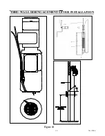
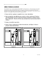
. Run cable for bowden lever (emergency disengagement lever pre-mounted on drive side, side
column cover) through pre-drilled hole in the head plate. Pull enough slack thru so that you can now
slide the 2’ section of the cable sheating on. Run cable down through the brake realease lever on the side
of the motor. Loop the cable thru the grid on the bottom of the motor fan cover and use the barrel clamp
supplied to fix the cable to the fan cover. Do not extra cable until final adjustments are made. (Figure 6)
Additional adjusting may be required once the sideframe cover is installed so that the brake release
works properly. Attach the other end of cable (with spring) to the bowden lever while installing drive
side cover profile at the same time. Secure cover profile at the top and bottom using supplied bolts
(Figure 7). Check and ensure that when you pull on the disengagement handle the door releases and can
be pulled up or down.
Step 17
. Install the remaining cover profile on the other side of the door using supplied bolts.
Step 18
. Attach barrel cover to both head plate mounting brackets using supplied screws and washers.
Place the side column covers over the head plates and attach using supplied screws.
Summary of Contents for 350016-0000
Page 3: ......
Page 12: ...12 Nov 2006 Figure 6 Figure 7 ...
Page 14: ...14 Nov 2006 THRU WALL DISENGAGEMENT LEVER INSTALLATION Figure 10 ...
Page 20: ...20 Nov 2006 ...


