background image


10 


         Nov. 2006 


Step 10

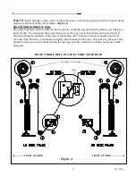
. Attach and place 2 pre-wraps of tensioning rope on both rope pulleys and allow rope to drape 

down over the front of the side columns. (Figure 4

Special instructions for rope 

The white rope does not so readily fit into the groove of the take up spool and requires a special step to 
allow for this. You must pull the single inner core of the rope out about 4 inches and cut it. This will 
help in reducing the diameter of the rope at the leading end. Then use a lighter to heat the end of the 
rope and roll it between your fingers to slightly shrink the end of the rope. This will give the rope some 
rigidity so that you can now thread it into the take up spool. Be careful not to burn your figures when 
doing this.


DO NOT DRILL HOLE IN TAKE UP DRUM FOR ROPE. 


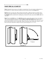
Knot 

Top Roll – 2 Prewraps 

Figure 4 

FRONT OF DOOR 

FRONT OF DOOR 

Summary of Contents for 350016-0000

Page 1: ...PART NUMBER 350016 0000 RAPID ROLL DOOR OWNER S MANUAL MODEL 355 VersionNovember 2006 975 A OLD NORCROSS ROAD LAWRENCEVILLE GA 30045 770 338 5000 TEL 770 338 5034 FAX 877 925 2468 TOLL FREE ...

Page 2: ...2 Nov 2006 WARNING DO NOT INSTALL OPERATE OR SERVICE THIS PRODUCT UNLESS YOU HAVE READ AND UNDERSTAND THE SAFETY PRACTICES WARNINGS INSTALLATION AND MAINTENANCE INSTRUCTIONS CONTAINED IN THIS MANUAL ...

Page 3: ......

Page 4: ... an Albany Door Systems representative This warranty does not cover damage caused by collision or other abuse of the product Adjustments made to the Control Panel or to the mechanical operation of the door without the authorization of Albany Door Systems will void this warranty The replacement provisions shall be the limit of Albany Door Systems responsibility under this warranty and Albany Door S...

Page 5: ...n 6 Maintain a clear door opening at all times Keep the door opening free of any obstructions 7 Remove power at the fused disconnect during all electrical or mechanical service OSHA requires a disconnect to be properly tagged and locked out during all maintenance or service of equipment 8 All electrical troubleshooting or service must be performed by a qualified electrician or service person and m...

Page 6: ...mbly 1 Drive Unit w torque arrestor bracket 1 Electrical Control Panel 1 Safety Photocells 1 set 1 Bottom Rail Profile 1 Counterbalance Springs 2 Tensioning Ropes 2 Width Gauge Assembly Hardware OPTIONAL PARTS Motion Detector Floor Loop Transmitters Auxiliary Pushbuttons Stations Pull Cords SUGGESTED TOOLS REQUIRED 5mm allen wrench Water Level 6mm allen wrench Carpenters Level 8mm allen wrench Ham...

Page 7: ... 3 Verify that the opening is plumb and that the floor slab is level Shimming may be required to level the side columns but no more then Refer to approval drawings for this door to confirm drive side mounting left or right hand Step 4 Remove the side columns from crate one at a time Remove covers from both side columns and set aside Remove springs and inner covers from both side columns Erect both...

Page 8: ...s on the head plates will make installing the width gauge easier along with the routing of the photocell cables Run wires under the back funnel and inside width gauge from non drive side to drive side of door These wires are for photocells contactless safety edge photocells and SRD2 sensors Figure 2 Slotted Holes ...

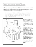
Page 9: ...gs are located outside the head plates Secure the top roll at both head plates on each side of door Figure 3 Step 8 Slide the drive unit onto the drive side stub axle Attach torque arrestor bracket to the head plate Step 9 Remove straps holding door fabric in place Disengage the drive unit brake by pulling down on the brake release lever and rotate the top roll until the bottom edge of the fabric ...

Page 10: ...You must pull the single inner core of the rope out about 4 inches and cut it This will help in reducing the diameter of the rope at the leading end Then use a lighter to heat the end of the rope and roll it between your fingers to slightly shrink the end of the rope This will give the rope some rigidity so that you can now thread it into the take up spool Be careful not to burn your figures when ...

Page 11: ...rake and manually move door over its entire range of motion Ensure that the fabric and windclips go behind the inner cover NOTE The door must be cycled 20 30 times to allow for the rope to stretch This will require you to make additional adjustments to the spring tension Once the stretching has settled you can then put the door into operation Be very sure that this is done before cutting the exces...

Page 12: ...12 Nov 2006 Figure 6 Figure 7 ...

Page 13: ...CKET TOP VIEW DRIVE UNIT 1 RUN BARE CABLE UP THROUGH SIDE FRAME AND SMALL HOLE IN BEARING PLATE CABLE SHEATH STARTS HERE RUN CABLE FROM TOP OF BEARING PLATE OVER TO DRIVE UNIT SECURE BARE CABLE TO BOTTOM OF MOTOR COVER USING SUPPLIED CABLE CLAMP ALSO REFER TO FIGURE 6 Figure 9 ...

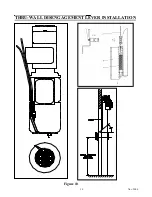
Page 14: ...14 Nov 2006 THRU WALL DISENGAGEMENT LEVER INSTALLATION Figure 10 ...

Page 15: ...TRICAL INSTALLATION ALSO ALL THREE PHASE POWER WIRES SHOULD BE RUN IN SEPARATE CONDUIT FROM ALL OTHER CONTROL CIRCUIT WIRING I E PULSE ENOCDER WIRING 1 Mount the control panel at a height of approximately four feet from the floor on the drive side of the door 2 Run electrical conduit and wires for pulse encoder cable drive unit power leads and receptacle cable Plug all wires into the electrical re...

Page 16: ... WIRE SIDE FRAME X35 PHOTOCELL RECEIVER 3 WIRE LEFT SIDE FRAME X36 PHOTOCELL TRANSMITTER 3 WIRE RIGHT SIDE FRAME X37 1 CSE RECIEVER 4 WIRE RIGHT SIDE FRAME X38 1 CSE TRANSMITTER 4 WIRE LEFT SIDE FRAME WARNING BEFORE APPLYING POWER TO CONTROL PANEL CHECK LINE VOLTAGE AT DISCONNECT WITH A VOLTMETER FIGURE 11 ...

Page 17: ...l Ensure the POWER LED s on both the PLC and frequency inverter are lit Also ensure that the RUN LED is lit on the PLC Step 3 Push the SETUP button The RESET light on the outside of the panel will come on and relay CR 11 will be energized at this point Using the OPEN CLOSE JOG DOOR button located on the control panel backplate small rocker switch jog the door in the close direction If the door clo...

Page 18: ...OR button When the door reaches the open limit proximity switch it will stop automatically and the open limit will be set The reset light should turn off at this point as well Step 3 Actuate door and observe the door limits open and closed Repeat steps 1 and 2 as necessary to finely adjust both door limits Step 4 Check all actuators for proper operation Step 5 Verify the automatic operation of the...

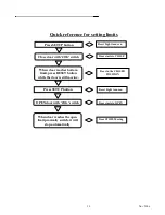
Page 19: ...ch Door starts to CLOSE When door reaches bottom limit press RESET button while the door is still moving Door in the CLOSED POSITION When door reaches the open limit proximity switch it will stop automatically Press SETUP button OPEN door with JOG switch Reset Light turns on Door starts to OPEN Door STOPS Moving ...

Page 20: ...20 Nov 2006 ...
Page 21: ...y photocells and bottom rail reset system QUARTERLY INSPECTION 1 Inspect all hardware for proper tightness Any loose hardware should be tightened It is recommended to apply a tread locker compound to any bolts that are coming loose i e Loctite 242 blue 2 Observe both open and close door limits Ensure a proper floor seal is intact when the door is fully closed There should be no visible light seen ...

Page 22: ... however To accomplish this perform the following procedure 1 Ensure the door opening is completely clear of any obstructions 2 Push and hold the blue SRD2 button on the face of the control panel The door will automatically close and re latch the bottom rail with the Contactless Safety Edge photocells The door will also stop automatically when the bottom limit is reached 3 Resume normal door opera...

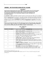
Page 23: ...t normal speed PLC INPUTS2 X0 X7 INPUTS IN LED S DESCRIPTION 0 Pulse encoder channel B a counting signal utilized by the PLC to keep track of door position Can be either on or off 1 Pulse encoder channel A a counting signal utilized by the PLC to keep track of door position Can be either on or off 2 SETUP button and top overrun proximity switch input will place door in setup mode reset button ligh...

Page 24: ...r direction To clear alarm condition remove power to control panel The most common cause of an inverter alarm is a motor current overload condition Ensure that the door is not jammed in any way and will move freely over the entire range of motion when the motor brake is manually released ...

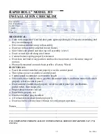
Page 25: ...of motion Photocells mounted on inside back profiles Factory Wired ELECTRICAL Fused disconnect installed and properly wired to control panel Three phase power available at control panel Control panel mounted at a serviceable height Drive unit door limit switches gearbox disconnect switch and brake motor kill switch properly wired to control panel Door actuators installed and properly wired to cont...

Reviews: