25 |
P a g e
THIS DOCUMENT IS SUBJECT TO CHANGE WITHOUT PRIOR NOTICE. SHOULD YOU HAVE ANY QUESTION, PLEASE FEEL FREE TO CONTACT OUR SALES
REV 1.0.2
Akribis Systems Pte Ltd
Blk 5012 Techplace II #01-05 Ang Mo Kio Avenue 5
Singapore 569876
Tel: +65 6484 3357 Fax: +65 6484 3361
RCB Reg No: 200410879N GST Reg No: 20-0410879-N
Diagnostic
1.
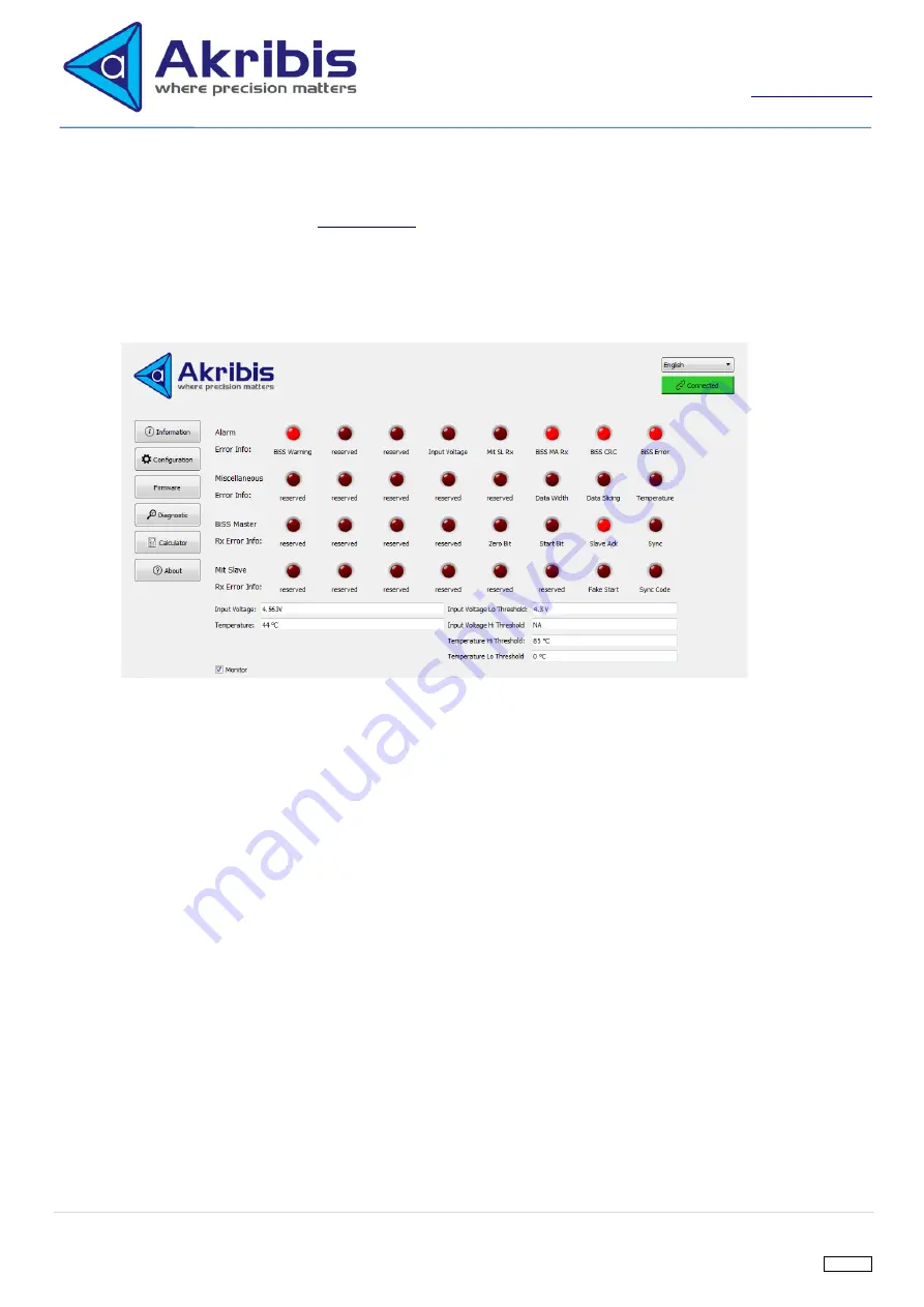
ITF-21-BISS-MIT will turn on red LED if error is detected. The root causes can be diagnosed with Diagnostic
page of PC software. Refer to
section for detail explanation of the adapter alarm info.
2.
C
lick on “Diagnostic” tab and the diagnostic page will be displayed.
3.
Tick the
“monitor” checkbox to monitor the diagnostic status.
The root cause of ITF-21-BISS-MIT alarm is the
one which its red LED is being turned on in the diagnostic page.
4.
First row of the red LED array is corresponded to Mitsubishi Alarm error. These LED shows the true Mitsubishi
Alarm error detected by the adapter. It does not take Mitsubishi Alarm Mask into consideration.
5.
The second row of red LED array is for error other than Mitsubishi Alarm.
6.
For alarm error like BiSS MA Rx and Mit SL Rx, they may be due to different root causes. These root causes
can be diagnosed quickly by checking on the BiSS Master Rx Error info row and Mit Slave Rx Error info of red
LED arrays respectively.
BiSS C Cycle Period Calculation
1.
The PC software also provide a calculator to do BiSS C Cycle period calculation
2.
User can key in the value into the respective
parameter and click “calculate” to quickly find out whether the BiSS
C cycle period is less than the maximum allowable BiSS C cycle period of ITF-21-BISS-MIT which is 102
μs
PC Software Version
1.
Click on “about” button to check whether the PC software version is up
-to-date.
It follows semantic versioning. The first official software version will be release as v1.0.0.


