background image

63  

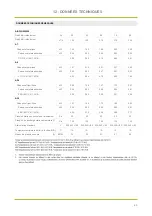
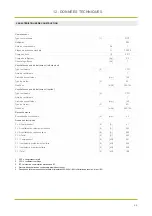
12 - DONNÉES TECHNIQUES


Débit d'air refoulement 

l/s 

35

42

58

75

89

Débit d'air refoulement 

m

3

/h 

125

150

210

270

320

A7  

Puissance thermique 

kW 

1,42

1,55

1,86

2,05

2,49

Puissance totale absorbée 

kW 

0,46

0,42

0,45

0,42

0,54

COP (EN 14511:2018) 

-

3,09

3,69

4,13

4,93

4,61

A-5

Puissance thermique 

kW 

1,97

2,10

2,21

2,37

2,45

Puissance totale absorbée 

kW 

0,40

0,52

0,47

0,37

0,32

COP (EN 14511:2018) 

-

4,93

4,04

4,70

6,50

7,66

A30  

Puissance frigorifique 

kW 

0,92

1,38

1,47

1,72

2,07

Puissance totale absorbée 

kW 

0,36

0,52

0,48

0,54

0,81

EER (EN 14511:2018) 

-

2,56

2,65

3,06

3,21

2,56

A35  

Puissance frigorifique 

kW 

1,57

1,64

1,73

1,92

2,23

Puissance totale absorbée 

kW 

0,36

0,52

0,53

0,55

0,81

EER (EN 14511:2018) 

-

4,34

3,15

3,26

3,50

2,77

Pression statique nominale de refoulement 

Pa 

50

50

50

50

50

Pression de décharge statique maximale (1) 

Pa 

120

120

120

120

120

Alimentation standard 

220-240/~/50

220-240/~/50

220-240/~/50

220-240/~/50

220-240/~/50

Température minimale de l’air à l'entrée (D.B) 

°C 

15-

15-

15-

15-

15- 

Niveau de pression sonore

         (2) 

dB(A) 

34

35

37

41

45

AIRFLOW2020

DONNÉES TECHNIQUES GÉNÉRALES 

Summary of Contents for AIRFLOW2020

Page 1: ...ly before installing or operating your new air conditioning unit Make sure to save this manual for future reference Installation operation Manual AIRFLOW2020 R32 Multilingual Manual French English 20...

Page 2: ......

Page 3: ...tentivement ce manuel avant d installer ou d utiliser votre produit Assurez vous de conserver ce manuel pour utilisation ult rieure Manuel d op ration d intallation AIRFLOW2020 R32 20 AW AIRFLOW2020 R...

Page 4: ...de qualit et de s curit L objectif de l entreprise est d offrir aux clients des syst mes modernes qui assurent le meilleur confort r duisent les consommations d nergie les co ts d installation et d e...

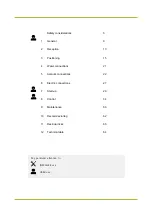
Page 5: ...3 15 4 21 5 22 6 27 7 29 8 34 9 53 10 62 11 63 12 64 Consid rations sur la s curit G n ralit s R ception Positionnement Raccordements hydrauliques Raccordements a rauliques Branchement le s ctriques...

Page 6: ...manuel Points de fixation de l unit Espaces fonctionnels B Installer les dispositifs antivibratoires fournis Joint antivibratoire en cas d utilisation de tubes rigides Dimensions raccords vacuation d...

Page 7: ...els DANGER La mauvaise installation d appareils ou d accessoires peut entra ner des d charges lectriques des courts circuits des fuites des incendies ou d autres dommages l appareil Il fait s assurer...

Page 8: ...rges lectriques et d un incendie ou peut entra ner la chute de l unit de son support Installer l unit sur une structure m me d en supporter le poids Une structure insuffisamment robuste peut entra ner...

Page 9: ...la temp rature ambiante ou porter des gants et des v tements de protection Ne pas toucher les pi ces internes pendant et juste apr s le fonctionnement Le contact avec les parties internes expose des...

Page 10: ...iel le dimensionnement des composants la section des c bles etc Si les pr requis d installation lectrique ne sont pas satisfaisants il est interdit de proc der l installation de l unit tant que l inst...

Page 11: ...9 NOTES...

Page 12: ...num ro de s rie 3 Ventilateur d extraction 4 Ventilateur de refoulement 5 Compresseur 6 changeur externe 7 changeur interne 8 Filtre air refoulement air ambiant 9 Filtre air expuls 10 Pompe d vacuatio...

Page 13: ...ATION DE L UNIT Lors de la commande de pi ces d tach es il faut founir ces indications Mod le num ro de s rie et num ro de produit Nom de la pi ce remplacer Formation utilisateur L installateur doit i...

Page 14: ...ements lectriques Avant de commencer les op rations s assurer d avoir le plan final pour la pose de l installation a raulique hydraulique lectrique et la position de l unit quipement recommand Jeu de...

Page 15: ...ttre recommand e avec accus de r ception adresser au transporteur et au fournisseur Les contestations doivent tre effectu es dans les 8 jours suivant la r ception les signalisations apr s CONTR LE LA...

Page 16: ...hors de port e des enfants les mat riaux d emballage car ils sont potentiellement dangereux Recycler et liminer le mat riau d emballage conform ment aux normes locales RETRAIT DES KITS L uni est four...

Page 17: ...n de permettre l acc s l unit pour les op rations d entretien Positionnement au plafond laisser la projection au sol de l unit libre et des espaces fonctionnels de fa on permettre l acc s par des esca...

Page 18: ...rres filet es M8 dans les triers pr vus sur l unit Ins rer la rondelle plate Visser l crou vitez de trop serrer les crous les ressorts s ils sont trop cras s ils n absorbent pas les vibrations a crou...

Page 19: ...ivibratoire sur la tige filet e Ins rer la rondelle plate et visser l crou pour bloquer viter de trop serrer les crous les ressorts s ils sont trop cras s ils n absorbent pas les vibrations Pour le po...

Page 20: ...18 3 POSITIONNEMENT ARMOIRE LECTRIQUE D visser les 4 vis Torx Acc s l armoire lectrique Couvercle en t le de l armoire lectrique fix par 4 vis torx...

Page 21: ...de mani re abaisser le couvercle arri re Faire attention au sens de rotation sinon le couvercle arri re risque d tre endommag Utiliser trois vis GB950 86 M4X20 pour installer le cou vercle arri re dir...

Page 22: ...e coupure de la sortie du c ble sur le c t inf rieur gauche Sortie du c ble c t inf rieur gauche Trou pour c ble Trou dans le mur et trou pour c ble Diam tre 8 10 R gler le couvercle avant puis le fix...

Page 23: ...liser les tuyaux d vacuation des eaux propres ou des gouts pour viter toute aspiration possible d odeurs en cas d vaporation de l eau contenue dans le siphon Le raccordement ne doit pas tre tanche l a...

Page 24: ...par Airwell afin d viter la p n tration d eau et lors du projet ils doivent avoir des caract ristiques limitant les chutes de pression afin de ne pas compromettre le bon fonctionnement de l unit Pour...

Page 25: ...il faut prendre soin d installer les tuyaux et les capuchons de toit non fournis par Airwell A 500 mm Dans les zones o les chutes de neige abondantes augmentent Capuchons de toit Tuyaux Grille d extr...

Page 26: ...tuyau flexible 1 Enfiler la partie perfor e en aluminium 2 Tirer la partie en polyester plastique Couches du tuyau flexible Isolant Aluminium perfor Gaine Film de polyester 3 Bien serrer l aide d un c...

Page 27: ...ir pouvant tre inspect S il y a un espace suffisant entre le faux plafond il est possible d am liorer encore l insonorisation en appliquant un rev tement au bo tier de distribution d air Utiliser une...

Page 28: ...action voir point pr c dent viter la proximit de fen tres terrasses balcons etc viter les zones face au vent viter les passages pour pi tons viter les garages caves greniers non a r s tablir les pi ce...

Page 29: ...oit tre qui p e d un raccordement de mise la terre efficace Installer l interrupteur diff rentiel selon les normes techniques en vigueur applicables aux installations lectriques et en vigueur dans le...

Page 30: ...ue de l unit le num ro du sch ma lectrique est indiqu sur la plaque signal tique B A D Carte principale S lecteur distance t hiver chaud froid Permet le changement du mode de fonctionnement de chauffa...

Page 31: ...et le transport peuvent avoir entra ner des desserrages Alimenter l unit en fermant le dispositif de sectionnement mais la laisser sur OFF Contr ler les valeurs de tension et de fr quence du secteur...

Page 32: ...stall e correctement et en conformit avec ce qui est indiqu dans ce manuel la ligne d alimentation lectrique de l unit est sectionn e au d part V rifications pr liminaires 1 Acc s en s curit 2 Les esp...

Page 33: ...on de l unit est comprise dans la plage 207 253 V 9 Contr ler l absence de vibrations anormales 10 Expliquer l utilisateur comment allumer teindre modifier le point de consigne et nettoyer les filtres...

Page 34: ...180 125 1 07 220 220 125 0 72 tuyau rectangulaire LxH d bit d air m3 h vitesse moyenne 250 80 125 1 74 300 100 125 1 16 400 120 125 0 72 D bits d air mesur s sur les bouches ext rieures ademission ex...

Page 35: ...33 NOTES...

Page 36: ...r programm e Avec une pression prolong e sur le param tre il est possible de le modifi rapidement OK Pour confirmer une op ration ON OFF Pour configurer la fonction ON OFF BACK Pour revenir au niveau...

Page 37: ...unit est en refroidissement et que le compresseur fonctionne TIMER indicateur allum lorsqu une minuterie valide est r gl e programme hebdomadaire ALARME indicateur allum lorsque se produit une panne...

Page 38: ...de la temp rature Appuyer sur LEFT RIGHT pour s lectionner Appuyer sur UP DOWN pour modifier Si aucune op ration n est effectu e dans les 3 secondes le syst me m morise automatiquement les configurat...

Page 39: ...la page d accueil Appuyer sur MENU pour revenir la page pr c dente MODE DE FONCTIONNEMENT S lectionner le mode avec UP et DOWN Confirmer avec OK Apr s 10 s sans actions le mode est m moris automatique...

Page 40: ...comme suit Timer quotidien S lectionner DAILY TIMER avec UP et DOWN puis appuyer sur OK Appuyer sur UP et DOWN pour s lectionner le Timer T1 T5 Appuyer sur ON OFF pour activer d sactiver le Timer s le...

Page 41: ...Timer s lectionn Appuyer sur LEFT RIGHT pour s lectionner chaque option configure Appuyer sur UP DOWN pour r gler la temp rature et les temps de d but et de fin Appuyer sur OK pour confirmer la confi...

Page 42: ...CK pour annuler l op ration et revenir la page pr c dente Lorsque AUTO TEMP SETTING ON la r gulation manuelle de la temp rature est d sactiv e c t de la page qui s affiche il est possible de modifier...

Page 43: ...breur sonore Time heure Date date Screen lock time blocage de l cran temps de 60 240 secondes par d faut 120 s AFFICHAGE DES ALARMES Appuyer sur MENU et s lectionner SERVICE INFORMATION S lectionner E...

Page 44: ...E INFORMATION S lectionner SERVICE PARAMETER Appuyer sur OK pour acc der Le menu est utilis par l installateur ou le technicien d assistance pour contr ler les param tres de fonctionnement Les param t...

Page 45: ...dans les 3 pages crans suivantes Appuyer sur UP DOWN pour faire d filer Appuyer sur Adjust pour modifier CONFIGURATION DESHUMIDIFICATION Appuyer sur MENU et s lectionner ASSISTANCE SETTING Ins rer PA...

Page 46: ...pour confirmer SUPPRESSION DES CONFIGURATIONS Restaurer tous les param tres configur s en usine S lectionner NO appuyer sur OK pour revenir la page pr c dente S lectionner YES appuyer sur OK pour conf...

Page 47: ...1 probe fault B E6 T4 probe fault B E7 Water level switch fault B E8 Module Board E Square type error fault B EE Module Board E Square error fault B E9 T2B probe fault B EA Tp probe fault B Eb EXV coi...

Page 48: ...B P9 SUPPLY DC protection du ventilateur C PA Protection du ventilateur DC EXHAUST C PP Protection insuffisante de la surchauffe de refoulement B L0 Protection du module C L1 Protection basse tension...

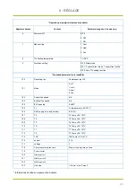
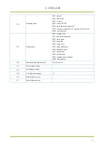
Page 49: ...C 1 04 AUTOSet1 Automatic temperature setting Y axis set point 1 25 0 50 C 1 05 EnOnOff Unit switch mode 0 ON OFF switch OFF signal is turned off ON boot 1 Wire controller control 2 Super terminal co...

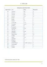
Page 50: ...7 EnProbeUrAmb Capteur d humidit int rieure 0 0 1 2 08 OffsetUrAmb Correction du capteur d humidit int rieure 0 50 50 3 01 Fr quence max en mode normal Fr quence maximale du compresseur en mode silenc...

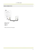
Page 51: ...49 8 R GLAGE MODBUS COMMUNICATION Modbus connection Baud rate 9600 Lenght 8 Parity none Stop bit 1 ModBus protocol details following pages KEYBOARD UNIT...

Page 52: ...fan 102 Supply fan speed 0 9 103 Exhaust fan speed 0 9 104 EXV opening 0 480P 105 Tc Tc temperature 25 70 C 106 RHC supply air reality humidty 0 100 107 T3 T3 Temp 25 70 C 108 T4 T4 Temp 25 70 C 109...

Page 53: ...tatus BIT0 electrical filter BIT1 gas deforst reserved BIT2 water pump BIT3 humidifier BIT4 4 way valve BIT5 exhaust fan power BIT6 supply fan power BIT7 system error BIT8 unit ON index BIT9 electrica...

Page 54: ...pFanSet 3 7 6 211 EnProbeUrExt 0 1 0 212 EnProbeUrSup 50 50 0 213 OffsetUrSup 0 1 0 214 OffsetUrAmb 50 50 215 EnAuxHeater 0 1 216 MaxAnAuxHeater 50 100 100 217 SlientMode 0 2 0 218 OffsetT1 10 10 0 21...

Page 55: ...lement l tat de colmatage Une inspection visuelle et un nettoyage fr quents au V rifier le filtre s il est tr s sale le remplacer ou le laver l eau Pour nettoyer laver l eau ti de avec un d tergent co...

Page 56: ...u prot g s de la corrosion Contr les des dispositifs lectriques La r paration et l entretien des composants lectriques doivent comprendre les contr les de Contr le de la zone Avant d effectuer toute o...

Page 57: ...s sur la base du r frig rant utilis aussi le bon pourcentage de gaz maximum 25 doit tre contr l En cas de panne pouvant compromettre la s curit aucun branchement lectrique ne doit tre effectu sur le...

Page 58: ...il sont ferm es En cas de fuite suppos e toutes les flammes nues doivent tre teintes ou loign es En cas de fuite de r frig rant n cessitant un brasage tout le r frig rant doit tre r cup r du syst me o...

Page 59: ...nement etc critiques entretien indispensable FR QUENCE DES INTERVENTIONS LIVRET DE L UNIT Pr voir un livret pour l unit sur lequel enregistrer les interventions effectu es sur celle ci Ceci permettra...

Page 60: ...ieur de Elfofresch Evo NETTOYAGE DE L INSTALLATION A RAULIQUE D SINFECTION D connecter les canaux de l unit D poser la grille Nettoyer les canaux Utiliser un aspirateur appropri couvrir l embout FILTR...

Page 61: ...terie test d coulement inspection nettoyage des filtres air mesure d bit d air trait canalisations contr le des fixations et dispositifs antivibratoires contr le fixation et isolation du c ble d alime...

Page 62: ...riodiquement la fermeture de tous les panneaux et leur bonne fixation En cas d incendie la temp rature du r frig rant peut atteindre des valeurs telles porter la pression au del de la valeur de s cur...

Page 63: ...uipement lectrique et lectronique m nager le fabricant recommande de contacter un revendeur agr ou une station cologique agr e L limination d un quipement lectrique et lectronique professionnel doit t...

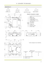
Page 64: ...W2 W3 W4 Points de fixation AE Reprise air neuf ES Extraction de l air Refoulement air ambiant Reprise air ambiant Reprise air neuf Refoulement air ambiant Extraction de l air Reprise air ambiant ESP...

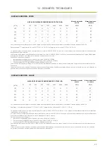
Page 65: ...fique kW 0 92 1 38 1 47 1 72 2 07 Puissance totale absorb e kW 0 36 0 52 0 48 0 54 0 81 EER EN 14511 2018 2 56 2 65 3 06 3 21 2 56 A35 Puissance frigorifique kW 1 57 1 64 1 73 1 92 2 23 Puissance tota...

Page 66: ...teurs 1 Diam tre du ventilateur mm 140 Type de moteur 3 EC D bit d air m3 h 400 125 vacuation des condensats 4 mm 32 Donn es lectriques F L A Compresseur 1 5 A 4 1 F L A ventilateur de refoulement uni...

Page 67: ...ssai par ex proximit de murs ou d obstacles en g n ral les niveaux sonores peuvent subir des variations importantes NIVEAU DE PUISSANCE SONORE BANDE D OCTAVE HZ Niveau de pression sonore Niveau de pui...

Page 68: ...possible du d bit d air souffl dans laquelle des cycles de d givrage peuvent se produire L unit peut fonctionner en modulation de d bit d air pour rester dans la plage de fonctionnement Les limites s...

Page 69: ...67 NOTES...

Page 70: ...68 NOTES...

Page 71: ...anual carefully before installing or operating your new air conditioning unit Make sure to save this manual for future reference Installation operation Manual AIRFLOW2020 R32 English 20 AW AIRFLOW2020...

Page 72: ...th high reliability efficiency quality and safety The target of the company is to offer advanced systems that assure the best comfort reduce the energy consumption the installation and maintenance cos...

Page 73: ...3 Positioning 15 4 Water connections 21 5 Aeraulic connections 22 6 Electric connections 27 7 Start up 29 8 Control 34 9 Maintenance 53 10 Decommissioning 62 11 Residual risks 63 12 Technical date 64...

Page 74: ...points Functional spaces B Install supplied antivibration Anti vibration joint when used rigid pipes Dimensions connections Condensate discharge D F Connect the ambient keyboard to the main board Ins...

Page 75: ...ment Make sure you only use accessories provided by the supplier which are designed specifically for the equipment and make sure they are installed by a professional All activities described in this m...

Page 76: ...ith the law local regulations and this manual Connect the unit to a separate power supply circuit An insufficient capacity of the power supply circuit or incorrect connections may lead to electric sho...

Page 77: ...ncrease abnormally if hit by lightning Do not wash the unit as it may cause electric shocks or fires Do not install the unit in the following places Where there is mineral oil even in form of vapour P...

Page 78: ...ted physical sensory or mental abilities Children must not play with the unit Cleaning and maintenance operations to be carried out by the user must not be performed by unsupervised children Once the...

Page 79: ...9 NOTES...

Page 80: ...number label 3 Exhaust fan 4 Supply fan 5 Compressor 6 External exchanger 7 Internal exchanger 8 ambient air supply air filter 9 exhaust air filter 10 Condensate drain pump 11 Air shutter actuator 12...

Page 81: ...indications such as Type of unit serial number 12 characters year of manufacture wiring diagram number electrical data Type of refrigerant Charge of refrigerant manufacturer logo and address The seri...

Page 82: ...work ensure you that have the final project for installing the aeraulic hydraulic elec tric drains and positioning the units Recommended instruments Set of Philips and flathead screwdrivers Cutters D...

Page 83: ...Contest by fax and registered mail with advice of receipt to supplier and the carrier Any disputes must be made within the 8 days owing the delivery Complaints after this period are invalid DELIVERY...

Page 84: ...xing strips Remove the packaging lifting it upwards Keep packing material out of children s reach it may be dangerous Recycle and dispose of packing material in conformity with local regula tions HMI...

Page 85: ...n the functional clearances to allow the access to the unit for the maintenance operations Ceiling positioning let free the projection to the ground of the unit and of the functional clearances to all...

Page 86: ...racket on the unit Insert the flat washer Screw the nut Do not over tighten the nuts the springs because if too much crushed they don t absorb vibrations FLOOR INSTALLATION a nut b flat washer c brack...

Page 87: ...readed bar the antivibration Insert the flat washer and tighten the nut to lock Do not over tighten the nuts the springs because if too much crushed they don t absorb vibrations For floor positioning...

Page 88: ...18 3 POSITIONING ELECTRIC PANEL Access to the electrical panel Sheet metal cover of the electrical panel fixed by 4 torx screws Remove the 4 torx screws...

Page 89: ...on in the bottom of keyboard and spin the screwdriver to take down the back cover Pay atten tion to spinning direction otherwise will damage the back cover Use three GB950 86 M4X20 screws to directly...

Page 90: ...itching wires Cutting place of left down side wire outlet Left down side wire outlet Wiring hole Wall hole and wiring hole Diameter 8 10 After adjusting the front cover and then buckle the front cover...

Page 91: ...etwork DO NOT use white water or drainage networks to avoid the aspiration of odours in the case of evaporation of water contained in the siphon The connection must not be hermetic so as to allow the...

Page 92: ...by Airwell so as to prevent water from entering During the design stage their features must limit load losses so as not to affect the correct operation of the unit To perform the ductings Connect the...

Page 93: ...oncentration of impurities dust odours exhaust fumes etc 2 Ambient air exhaust away from terraces balconies property boundary lines avoid windward zones 2 1 Insulated flexible pipe Rooftop exhaust ret...

Page 94: ...pipe fixing 1 Introduce the perforated aluminium part 2 Pull the polyester part down plastic Layers of the flexible pipe 3 Tighten well using the strap Insulating Perforated aluminium Sheath Polyester...

Page 95: ...box Use soundproof material low density polyester fibre is recommended Box Plasterboard Access trap door Warning During the installation carefully close all the open points of the aeraulic system as...

Page 96: ...r exhaust Choose the position of the exhaust outlet see previous point avoid positions close to windows terraces etc avoid windward zones avoid pedestrian passages avoid unventilated attics garages ba...

Page 97: ...reepage breaker must be installed adjacent to the power supply Set the electric leakage protector according to the relevant electric technical standards of the State After wire connection check it aga...

Page 98: ...ber of the diagram is shown on the serial number label B A C Remote summer winter selector switch heat cool It allows the change of the operating mode from heating to cooling from an external control...

Page 99: ...e dampers are opened and calibrated the air filters are not removed from unit and are cleaned possible ventilation checks and the operating starting period determinate a ducting cleaning with conseque...

Page 100: ...oints to check and of the operations to perform to start up the unit For details refer to the various chapters in the manual Before starting the unit make sure that the room is free of dust and debris...

Page 101: ...vibrations check 10 Instruct the customer on how to switch the device on off change the set point and clean the filter 11 Collect all the machine documentation and give it to the customer together wi...

Page 102: ...m s 140 140 125 1 77 180 180 125 1 07 220 220 125 0 72 rectangular tube LxH airflow m3 h speed medium m s 250 80 125 1 74 300 100 125 1 16 400 120 125 0 72 Airflows measured on the external inlets ou...

Page 103: ...33 NOTE...

Page 104: ...or modify the set value The parameter can be rapidly modified by pressing it extendedly OK To confirm an operation ON OFF To set the ON OFF function BACK To return to the previous level Press to exit...

Page 105: ...or on when the unit is in cooling and the compressor is running TIMER indicator on when a valid timer has been set weekly schedule ALARM indicator on when a fault occurs or a protection device interve...

Page 106: ...ed off The password is required to disable the timer Adjustment Temperature Press LEFT RIGHT to select Press UP DOWN to change If no operations are made for more than 3 sec the system automatically me...

Page 107: ...page Press MENU to return to the previous page Operating mode Choose the mode with UP end DOWN Confirm with OK After 10 sec without any operation the mode is memorised automatically Function enabled...

Page 108: ...the display will appear as follows Daily timer Select DAILY TIMER with UP end DOWN and press OK Press UP end DOWN to choose timer T1 T5 Press ON OFF to enable disable the selected timer Press LEFT RI...

Page 109: ...e selected timer Press LEFT RIGHT to select each option to be set Press UP DOWN to adjust the temperature and start end time parameters Press OK to confirm the setting and return to the previous page...

Page 110: ...the operation and return to the previous page When AUTO TEMP SETTING ON manual adjustment of the temperature is disabled Shown to the side is the page that appears when the user attempts to modify the...

Page 111: ...cicalino Time ora Date data Screen lock time Screen lock time from 60 to 240 seconds default 120sec VISUALIZATION OF ALARMS Press MENU end select SERVICE INFORMATION Select ERROR CODE and insert PASSW...

Page 112: ...and select SERVICE INFORMATION Select SERVICE PARAMETER Press OK to access The menu is used by the installer or service technician to check the operating parameters The parameters are displayed in the...

Page 113: ...Press UP DOWN to scroll Press Adjust for modification DEHUMIDIFICATION SETTING Press MENU and select ASSISTANCE SETTING Insert PASSWORD Press OK Select Humidity parameter Enable parameter 2 01 EnProbe...

Page 114: ...ar all alarms Select YES press OK to confirm CANCEL ASSISTANCE SETTING Reset all the factory set parameters Select NO press OK to return to the previous page Select YES press OK to confirm RESET COMPR...

Page 115: ...ult B E7 Water level switch fault B E8 Module Board E Square type error fault B EE Module Board E Square error fault B E9 T2B probe fault B EA Tp probe fault B Eb EXV coil fault B EU URsu probe fault...

Page 116: ...heating mode B P9 SUPPLY DC fan protection C PA EXHAUST DC fan protection C PP Insufficient protection of discharge superheat B L0 Module protection C L1 Low Voltage Protection C L2 High Voltage Prote...

Page 117: ...4 AUTOSet1 Automatic temperature setting Y axis set point 1 25 0 50 C 1 05 EnOnOff Unit switch mode 0 ON OFF switch OFF signal is turned off ON boot 1 Wire controller control 2 Super terminal control...

Page 118: ...robeUrAmb Indoor humidity sensor 0 0 1 2 08 OffsetUrAmb Indoor humidity sensor correction 0 50 50 3 01 Max frequence in normal mode Maximum frequency of compressor in normal silent mode 60 56 72 HZ 3...

Page 119: ...49 8 CONTROL MODBUS COMMUNICATION ModBus protocol details following pages Modbus connection Baud rate 9600 Lenght 8 Parity none Stop bit 1 KEYBOARD UNIT...

Page 120: ...de 0 off 1 cooli 2 heat 3 fan 102 Supply fan speed 0 9 103 Exhaust fan speed 0 9 104 EXV opening 0 480P 105 Tc Tc temperature 25 70 C 106 RHC supply air reality humidty 0 100 107 T3 T3 Temp 25 70 C 10...

Page 121: ...tatus BIT0 electrical filter BIT1 gas deforst reserved BIT2 water pump BIT3 humidifier BIT4 4 way valve BIT5 exhaust fan power BIT6 supply fan power BIT7 system error BIT8 unit ON index BIT9 electrica...

Page 122: ...mAux 10 120 20 210 SupFanSet 3 7 6 211 EnProbeUrExt 0 1 0 212 EnProbeUrSup 50 50 0 213 OffsetUrSup 0 1 0 214 OffsetUrAmb 50 50 215 EnAuxHeater 0 1 216 MaxAnAuxHeater 50 100 100 217 SlientMode 0 2 0 21...

Page 123: ...y and cleaned at least every 6 months Check the filter replace if very dirty or wash it with water To clean clean in tepid water with common detergent rinse thoroughly in running water to avoid spilla...

Page 124: ...nting phases That the earth conductor is continuous Area checks Before working on systems containing flammable refrigerants perform safety checks to reduce the risk of combustion to the minimum Before...

Page 125: ...ting the system vacuum with OFN and filling until the operating pressure is obtained then releasing into the atmosphere and restoring the vacuum This process must be Repairing sealed components During...

Page 126: ...cover flammable refrigerants A series of perfectly functioning calibrates scales must also be available Flexible tubes must be equipped with leak proof disconnection fittings in good condition Before...

Page 127: ...process must be performed before taking the compressors back to the suppliers The electric resistance must be used with the compressor body only to accelerate this process Operations to discharge the...

Page 128: ...the operating limits etc critical use service necessary INSPECTIONS FREQUENCY UNIT BOOKLET It s advisable to create a unit booklet to take notes of the unit interventions In this way it will be easie...

Page 129: ...tion Cleaning of the aeraulic system is to be carried out by a specialised technician trained in aeraulic hygiene air processing in compliance with technical regulations and national local regulations...

Page 130: ...flow test air flow rate measurement channelling anti vibration devices and fastenings check power supply cable isolation and fastening check earth cable check power remote controls state clamps closur...

Page 131: ...Periodically check that all of the panels are correctly closed and fixed If there is a fire the temperature of the refrigerant could reach values that increase the pressure to beyond the safety valve...

Page 132: ...edor autorizado o a una isla ecol gica autorizada La eliminaci n de un aparato el ctrico y electr nico profesional tiene que efectuarse por personal autorizado mediante los consorcios espec ficamente...

Page 133: ...st Ambient air return Removable panel for bottom access to the air filter Electric p al anel Power input keyboard connection Auxiliary connection Condensate drain connection Emergency drain W1 W2 W3 W...

Page 134: ...ng capacity kW 0 92 1 38 1 47 1 72 2 07 Total power input kW 0 36 0 52 0 48 0 54 0 81 COP EN 14511 2018 2 56 2 65 3 06 3 21 2 56 A35 Cooling capacity kW 1 57 1 64 1 73 1 92 2 23 Total power input kW 0...

Page 135: ...f fans 1 Fan diameter mm 140 Type of motor 3 EC Airflow mc h 125 400 Connections Condensate drain 4 m 4 32 Electircal data F L A Compressor 1 5 A 4 1 F L A Single supply fan 5 A 0 62 F L A Single exha...

Page 136: ...significantly if the unit is installed in different conditions ex with surrounding obstacles walls or similar SOUND POWER LEVEL DB OCTAVE BAND HZ Sound power level Sound pressure level 63 63 12 250 5...

Page 137: ...ion defrosting may occur The unit can modulate the air flow rate in order to keep operating in the operating range The limits are meant as a guide Please note that they have been calculated by conside...

Page 138: ...68 NOTE...

Page 139: ...74 NOTE...

Page 140: ...with the sales agency or manufacturer for details ATTENTION Le design et les donn es techniques sont donn s titre indicatif et peuvent tre modifi s sans pr avis AIRWELL RESIDENTIAL SAS 10 rue du Fort...

Reviews: