


20
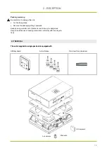
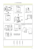
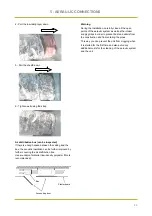
3 - POSITIONING
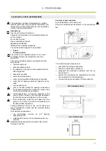
Buckling
position
Straight head
screwdriver
Back cover
Front cover
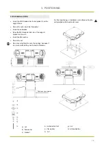
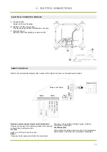
Screw hole installed on the wall,use
three GB950-86 M4X20
Screw hole fixed on the wall,use one
GB950-86 M4X20
A
- Screw hole installed on 86 Electri-
cian box, use two M4X25 GB823-88
Back cover
Signal
switching
wires
Cutting place of left
down side wire outlet
Left down side
wire outlet
Wiring hole
Wall hole and wiring hole
Diameter 8--10
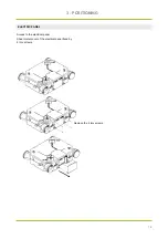
After adjusting the front cover and then buckle the front
cover; avoid clamping the communication switching wire
during installation.
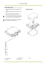
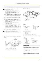
Sensor can not be
affected with damp.
A
Electri
cian box
B
C
B
C
B -Trap
C - Putty
C
B
Avoid the water enter into the
wired remote controller, use trap
and putty to seal the connectors
of wires during wiring installation.
Summary of Contents for AIRFLOW2020
Page 2: ......
Page 11: ...9 NOTES...
Page 35: ...33 NOTES...
Page 69: ...67 NOTES...
Page 70: ...68 NOTES...
Page 79: ...9 NOTES...
Page 103: ...33 NOTE...
Page 138: ...68 NOTE...
Page 139: ...74 NOTE...