Page 32
aERO MODEL TyPE
Changing Servo Centering Percentage Values, Continued....
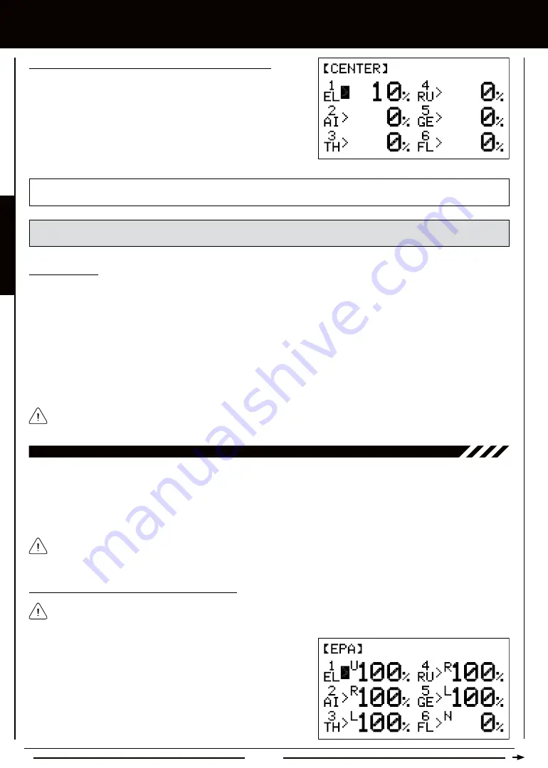
3) Press the Navigation Pad
5634
to highlight the channel that you
would like to change the Servo Centering percentage value for.
4) Press the INC+/M1 or DEC-/M2 keys to change the Servo Centering
percentage value to center the servo horn.
5) Repeat steps 3 and 4 to center the servo horns for the desired remaining
channels.
CENTER setting range is -150% to 150%. The default setting is 0%. Increase or decrease the Servo Centering percentage
values to center the servo horns.
WARNING
We don't recommend using a Servo Centering percentage value outside the range of approximately -40% to
40%. Using a percentage value outside of this range can result in limited maximum servo travel.
Zeroing Out Trim
Although trim switch settings are automatically stored in memory for each individual model, some users may wish to always keep
their trim switch settings at zero (centered) for all models. For example, after test-flying your model, if you have had to add trim to
make your model fly straight and level, you can use the Servo Centering function to add that amount of trim back into the servo(s),
then move the trim switches back to center. This ensures that your trim switches are always centered.
1) After flying your model, check your model's control surfaces to see how much trim was necessary to achieve straight and level flight.
2) From within the CENTER menu, highlight the channel you need to add Centering trim to.
3) Recenter the trim switch, then change the Servo Centering percentage value until the control surface is in the same position
it was prior to recentering the trim switch.
Double-check the control throws to ensure the End Points haven't changed.
In the default configuration, the same trim settings are stored across all Flight Modes. This option can be changed to
allow you to store different trim settings for each individual Flight Mode. For more information, see page 36.
10.EPa (EnD POinT aDjUSTMEnT)
The End Point Adjustment function allows you to adjust servo travel in each direction. This makes it possible to balance control
surface throw in both directions and set the maximum desired control throw. For example, if you want your elevator to move Up
and Down two inches in each direction, but the elevator moves Down more than two inches, decrease the End Point Adjustment
in the Down direction, so that the elevator moves Up and Down the same amount. Another example is with ailerons. If your
aircraft rolls faster to the right than to the left, increase the End Point Adjustment in the Left direction until the aircraft rolls the
same speed in both directions.
The End Point Adjustment function is designed to balance the control throw on both sides of servo travel and can be
overridden by other settings, such as Dual Rate. For example, if you have your End Point Adjustment percentage value set
to 100%, and you set your Dual Rate percentage value to 150%, the servo will travel more than 100% when Dual Rate is ON.
1) From the Display screen, press the ENTER key to display the Programming
Menus.
2) Press the Navigation Pad
56
to highlight EPA, then press the ENTER
key to display the EPA menu. The cursor will default to 1EL>U100% or
1EL>D100% depending on the last position of the elevator control stick.
The channel numbers will differ based on the Model Type selection options you chose previously in the TYPE menu.
For example, if you chose AILE>2, channel 2 will be displayed as LA (Left Aileron) and channel 5 will be displayed as
RA (Right Aileron).
Changing End Point Adjustment Percentage Values
Summary of Contents for SD-6G
Page 1: ...Page 1...


