3. Electric System
3-22
10. List of functions
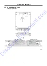
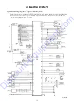
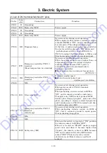
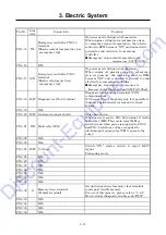
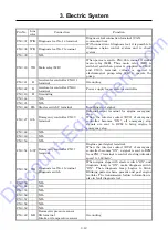
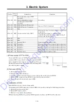
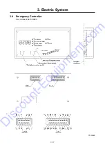
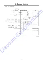
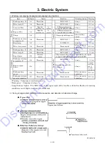
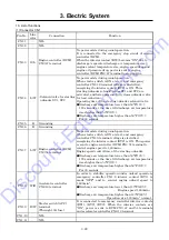
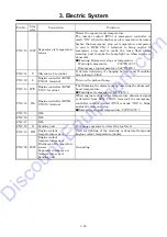
(1) Connector CN1
Pin No. Line
color
Connection Function
CN1-1
-
NIL
CN1-2
-
NIL
CN1-3 G/L Engine controller (ECM)
CN3-47 terminal
No power exists during usual operation.
It is connected to the emergency stop circuit of engine
controller (ECM).
When the interior contact (RY3) becomes “ON” due to
discharge / separator discharge air temperature rise,
engine coolant temperature rise, engine speed drop and
engine oil pressure drop, power is sent to engine
controller (ECM) CN3-47 terminal to stop engine.
CN1-4 L/W
・
Solenoid valve for starting
unloader SV1, SV2
No power exists during usual operation.
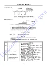
When starter switch is ON at start, and emergency
controller CN1-12 terminal voltage is electrified,
energizing the interior contact (RY4) is
ON. Thus
starting unloader solenoid valves SV1 and SV2 are
activated, and lower pressure fully closes unloader valve
for load reduction.
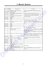
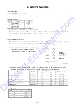
Operating time of the starting unloader solenoid valve
●
Discharge air temperature lower than 50°F(10
℃
):
120 seconds or the time till discharge air temperature
rises higher than 50°F(10
℃
).
●
Discharge air temperature higher than 50°F(10
℃
):
For 30 seconds
CN1-5 B Grounding
CN1-6 B Grounding
CN1-7 L/W Engine controller (ECM)
CN3-51 terminal
No power exists during usual operation.
When starter switch is ON at start, and emergency
controller CN1-9 terminal voltage is electrified,
energizing the interior contact (RY2) is
ON. Thus power
is sent to engine controller (ECM) CN3-51 terminal to
control engine speed to 1,600min
-1
.
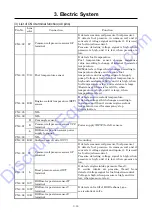
Engine speed control time of the starting unloader.
●
Discharge air temperature lower than 50°F(10
℃
):
120 seconds or the time till discharge air temperature
rises higher than 50°F(10
℃
).
●
Discharge air temperature higher than 50°F(10
℃
):
For 30 seconds
CN1-8 W/R Accelerator controller
CN6-18 terminal
In order to stabilize operation under unload operation,
emergency controller CN1-8 interior contact (RY1) is
made “OFF” and to control engine unload speed to
1,600min
-1
.
●
Discharge air temperature lower than 140°F(60
℃
):
Engine speed 1,600min
-1
●
Discharge air temperature higher than 140°F(60
℃
):
Operation at a 1,300min
-1
normal.
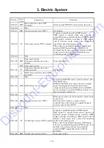
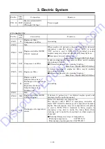
CN1-9 R/W
Starter switch [ACC]
terminal
(Through 10A fuse)
It is connected to emergency controller interior contacts
(RY1), (RY2), (RY3). When the interior contacts are
“ON”, power is sent to ECM CN3-47 and 51 terminals
and accelerator controller CN6-18 terminal.
CN1-10
-
NIL
CN1-11
-
NIL
Discount-Equipment.com
Summary of Contents for PDS400S-6C3
Page 1: ...www discount equipment com D i s c o u n t E q u i p m e n t c o m ...
Page 10: ...1 Specification 1 4 PC14064E Unit mm D i s c o u n t E q u i p m e n t c o m ...
Page 19: ...1 Specification 1 13 Aftercooler type A120195E D i s c o u n t E q u i p m e n t c o m ...
Page 20: ...1 Specification 1 14 1 8 Fuel Piping PC13053E D i s c o u n t E q u i p m e n t c o m ...
Page 101: ...5 3 5 2 Engine Wiring Diagram PC13087E PC13088 D i s c o u n t E q u i p m e n t c o m ...

