2. Maintenance
2-11
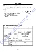
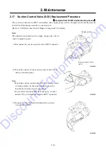
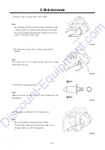
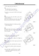
2.7
Change Oil Separator
●
When consumption of the oil is still unusual even after cleaning strainer in the scavenging orifice,
change the oil separator with a new one.
●
When replacing oil separator, be sure to replace gasket too.
<Procedure>
①
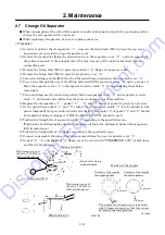
In order to pull out the oil separator
“
1
”
, unscrew the fixing bolts (M8, 4 pieces) for top cover
inspection cover provided on top of separator cover.
②
Remove the bracket for fixing the solenoid valve on the separator cover
“
2
”
and also remove all
the cables connected to the solenoid valve. Further, remove all the nylon tubes fixed on cable
connecting parts.
③
Remove the fixing bolts (M12, 4 pieces) provided at
flange of separator outlet.
④
Remove the fixing bolts (M12, 8 pieces) of separator cover
“
2
”
.
⑤
Screw two lifting eyebolts (M12) for the 2 threaded holes provided on the separator cover
“
2
”
.
⑥
Pass a rope through the eyes of the lifting bolts and lift the separator cover
“
2
”
up by a crane etc.
Mark the separator cover
“
2
”
and separator receiver tank
“
3
”
for reassembling them before
removing it.
⑦
Clean and degrease the connecting portion between separator cover
“
2
”
and separator receiver
tank
“
3
”
and check and confirm that there are no damages nor abnormalities.
⑧
Replace the oil separator
“
1
”
, gasket
“
4
”
,
“
5
”
and
flange of gasket (1 piece) by new ones.
⑨
At the point where gasket
“
4
”
and
“
5
”
contact the oil separator, staple
“
6
”
is to be pinned in four
points (diagonally) for prevention of static electricity. The staples
“
6
”
of gasket
“
4
”
and
“
5
”
should
be stapled not being overlapped.
※
HD-35 of MAX CO. LTD., should be used.
⑩
Tighten the fixing bolts of separator cover
“
2
”
according to the specified torque.
(Tighten the bolts diagonally and after tightening all the bolts, ultimately tighten them again in
full circumference.)
⑪
Tighten the fixing bolts of
flange according to the specified torque.
⑫
Connect re-assemble the pipes which were removed from the top of separator cover
“
2
”
.
※
Gasket
“
4
”
,
“
5
”
and gasket of
flange are to be coated with “THREEBOND 1212” at both faces
and then to be tightened.
PDS400SC-6C3
A120182
PC12096
Bracket for fixing
solenoid valve
A
Tightening torque of
the bolts: 752.2lbf
・
in
(85N
・
m)[845kgf
・
m]
Lifting bolt (M12)
4
1
5
Tightening torque of
the bolts: 752.2lbf
・
in
(85N
・
m)[845kgf
・
m]
2
3
Lifting bolt (M12)
Position of the stapler
Position of the stapler
the upper gasket
Position of the stapler
the lower gasket
(4 places)
(4 places)
(Center)
The staples of both gaskets are to be fixed
with 45 degree changed so that they cannot
be fixed at the same position.
Discount-Equipment.com
Summary of Contents for PDS400S-6C3
Page 1: ...www discount equipment com D i s c o u n t E q u i p m e n t c o m ...
Page 10: ...1 Specification 1 4 PC14064E Unit mm D i s c o u n t E q u i p m e n t c o m ...
Page 19: ...1 Specification 1 13 Aftercooler type A120195E D i s c o u n t E q u i p m e n t c o m ...
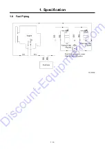
Page 20: ...1 Specification 1 14 1 8 Fuel Piping PC13053E D i s c o u n t E q u i p m e n t c o m ...
Page 101: ...5 3 5 2 Engine Wiring Diagram PC13087E PC13088 D i s c o u n t E q u i p m e n t c o m ...

