Page
4
of
30
15C0233-00 Rev A
SSC4500DX
9/23/2020
Sequence Of Operation
Initial Power Up:
Upon powering up, there is a 15 second ON-DELAY timer. This allows the LOGO PLC controller
to power up, to perform its internal diagnostics, to validate all sensors, and to confirm all inputs
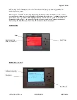
are reading and functioning properly. The main display screen will be established and display
the following: Date, Time, Temperature (°F), Humidity % RH, and Pressure
“WC.
Establish Continuous Air Circulation and Positive Pressure:
Once the initial power-up timer has expired, the evaporator fan will be energized, it will run
continuously so long as the cabinet is powered. A 30 second ON-DELAY timer will be activated;
this will allow sufficient time to establish air recirculation and positive internal pressure.
The internal cabinet pressure will be continuously monitored, displayed, and alarmed. The
minimum internal pressure is 0.03
”WC. If the internal pressure drops below the pressure limit, a
60-second ON-DELAY timer will be activated. After 60 seconds, if the pressure is not at or
above the 0.03
”WC, an alarm will be triggered. The display screen will change to red and the
alarm condition will be displayed along with the date of the alarm, the time, and corrective
action. The REMOTE ALARM RELAY will be energized during this alarm condition. Once the
pressure is re-established above the 0.03
”WC, the alarm relay will de-energize and the display
will clear and return to the default screen. This condition typically occurs when hospital
personnel open the cabinet door to supply or retrieve medical equipment from the cabinet; when
the door is open, the internal pressure goes to zero. This function will also detect a failed
evaporator fan or a heavily loaded HEPA filter that needs replacement.
Temperature Control:
The internal cabinet temperature will be monitored and compared to the TEMPERATURE SET
POINT (range 65-75°F user selectable default 70°F). The temperature will be controlled by
pulsing of a 500W heater by a solid-state relay (SSR).
The following safeties will be incorporated to continuously protect both the compressor and
heater. An HPS (high pressure switch) will continuously monitor the discharge pressure of the
compressor and open at a predetermined value. If the HPS is open, the compressor/condenser
fan will be de-energized. The display screen will change to red and the alarm condition will be
displayed along with the date, the time of the alarm, and corrective action. The REMOTE
ALARM RELAY will be energized during this alarm condition. An HTCO (auto re-set high
temperature cutoff) will continuously monitor the air temperature in the evaporator exit chamber.
If the HTCO is open, the heater output will immediately be de-energized until the switch closes.
The display screen will change to red and the alarm condition will be displayed along with the
date, the time of the alarm, and corrective action. The REMOTE ALARM RELAY will be
energized during this alarm condition.
The Compressor/Condenser fan will operate continuously to maintain a constant off-coil
temperature for dehumidification control. The 500W heater will be modulated (PWM) based on a
PID-type loop controller specific to the LOGO controller. If the measured temperature exceeds
the TEMPERATURE SET POINT plus 2°F, a 120 second timer will be initiated. If after 120
seconds the temperature has not dropped below the TEMPERATURE SET POINT plus 1 °F,
the screen will change to red and the alarm condition will be displayed. The REMOTE ALARM
RELAY will be energized. Once the measured temperature drops to TEMPERATURE SET
POINT plus 1 °F, the alarm relay will de-energize and the display will clear.


