3
Interfaces
3.1 Serial Data Interface
AT-1 is capable of interfacing with other aviation instruments by sending and/or receiving
serial data on its three serial data ports. All three serial data ports can be configured
individually.
Pin Name
Pin number
I/O
RS-232 Port 1 data out (TXD1)
1.11
Out
RS-232 Port 1 data in (RXD1)
1.2
In
RS-232 Port 2 data out (TXD2)
1.12 / 2.2
Out
RS-232 Port 2 data in (RXD2)
1.3 / 2.3
In
RS-232 Port 3 data out (TXD3)
1.13
Out
RS-232 Port 3 data in (RXD3)
1.4
In
The serial inputs/outputs conform to RS-232C (EIA Standard) with a positive and a negative
output voltage of at least 5V when driving a standard RS-232 load.
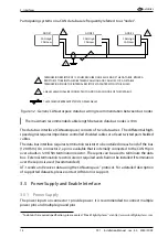
It is not sufficient that power supply ground on both devices is connected to aircraft
ground. An additional direct ground connection is mandatory.
The use of a twisted pair shielded cable, e.g. MIL-C-27500-22TG 2T14 is highly recommended.
With this cable both data wires and the GND reference can be connected using a single
cable.
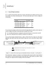
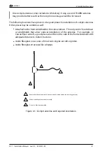
SYSTEM 1 RS-232 send data (TX)
SYSTEM 1 RS-232 receive data (RX)
SYSTEM 1 Ground (GND)
SYSTEM 1 POWER (VIN)
SYSTEM 2 RS-232 receive data (RX)
SYSTEM 2 RS-232 send data (TX)
SYSTEM 2 Ground (GND)
SYSTEM 2 POWER (VIN)
-
-
-
-
"SYSTEM 1"
-
-
-
-
DIRECT GND-CONNECTION VIA SHIELD OR EXTERNALLY IS REQUIRED FOR ALL RS-232 CLIENTS
AIRCRAFT POWER (+)
AIRCRAFT GND (-)
AIRCRAFT GND (-)
AIRCRAFT POWER (+)
1
1
THIS SYMBOL REPRESENTS TWISTED PAIR CABLES
"SYSTEM 2"
Figure 3.1.: Generic RS-232 wiring recommendation between ‘‘System 1’’ and ‘‘System 2’’
The table below contains maximum recommended cable lengths when using shielded
data cables for an RS-232 data interface. Exceeding these cable lengths may reduce signal
integrity and compromise the reliability of the data interface.
12
AT-1
·
Installation Manual
·
rev. 4.0
·
2020/01/09

