Initial Operation
6. INITIAL OPERATION
Sensor connection
Connect transducers to the sockets
M0
to
M8
(1),
s. 8.
Power supply
with accumulators or mains adapter on DC (5) s. 7.1, 7.2
Switch-on
Move the left slide switch (1) upwards,
s. 7.5
Automatical display of the last measuring menu,
s. 10.
keys
:
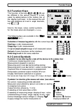
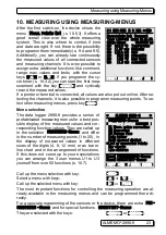
Menu selection
MEAS.-Menus:
call up with key:
< ESC >
or
F4
e.g. select menu
StandardDisplay
,
s. 9.1
/
... (
F
)
Call up the menu with key:
Select meas. point
(s. 10.1.1)
with keys:
/
... (
M
)
Select function
Max/MinVal
(s. 9.4)
with:
PROG
,
...
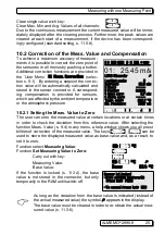
Clear max/min values,
s. 10.1.2
< CLR >
or
F1
Output of measuring data or memory via interface:
- Connect peripheral device, via data cable, to socket
A1
(3), s. man. 5.2
- Set 9600bd, 8 data bits, 1 stop bit, no parity at peripheral device
Single output
/storage,
s. 10.3.1
< MANU >
or
F2
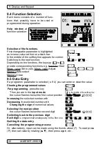
Cyclic measurement:
Select
Cycle-Timer
:
PROG
,
...
Enter cycle (hh:mm:ss)
s. 9.5
Cycle-Timer:
00:05:00
Sn
Output format list ´
´, columns ´
n
´, table ´
t
´
< FORM>
or
F3
...
Stop programming
< ESC>
or
F4
Start/stop the cyclic measurement,
s. 10.3.2
<START>
,
<STOP>
or
F1
Output of memory data
to printer or computer:
Select the function
Memory Free
with:
PROG
,
...
Memory data output,
s. 11.2.6
< PRINT>
or
F3
Clear memory,
s.
< CMEM >
ALMEMO
®
2890-9
15
F1
F2
|
F3
F4
ON PROG
F1
F2
|
F3
F4
ON PROG
* ALMEMO 2890-9 *
±±±±±±±±±±±±±±±±±±±±±±±±±±±±±±±±±±±±
MEASURING-Menus:
Standard display ©
U1 Meas. value correction
U2 Averaging
U3 Volume flow
Data logger
Multi channel display
*List of measuring points
Bar charts
Line diagram
_____________________
Menu1 PROGRAMMING-Menus
Menu2 ASSISTANT-Menus
POFF *ON F MENU1 MENU2
C © REC COM l© ©l R01 * ´´´´´´µµµµ
¯¯¯¯¯¯¯¯¯¯¯¯¯¯¯¯¯¯¯¯¯
01:
Velocity
m/s
æ
» H º
28.67
Maximum value:
31.34 mls
Minimum value:
25.37 mls
Cycle-timer:
00:02:30 Un
Memory free:
512.0 kB
START MANU M PRINT ESC


