background image


AG-tronik M1 AND REGULATOR PR-9 

INSTRUCTIONS FOR USE – rev. 2017-04


64 

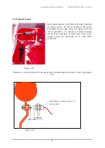
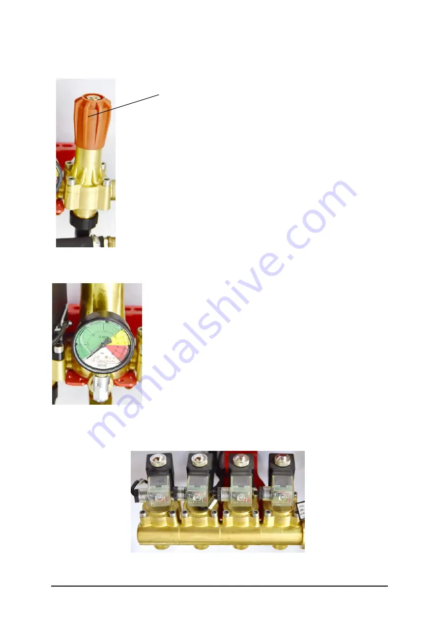
15.3. Manual regulation valve 


Regulating nut 
 
 
Manual  regulation  valve  is  for  manual  settings  of 
maximum pressure in system, that is in sprayer. In fact this 
is  safety  valve,  which  can  be  adjusted  with  the  nut.  The 
pressure  is  increasing  by  turning  the  nut  in  clock  wise 
direction  and  vice  versa.  The  control  of  pressure  is  0–20 
bar.  


     Figure 112 


15.4. Pressure gauge  


As  standard,  pressure  regulator  is  fitted  with  pressure  gauge 
with diameter of 63 mm, class 1.6. Measurement range is 0–30 
bar. The scale is divided into a colour ranging from 0–20 bar 
in  green,  20–25  bar  is  yellow  and  25–30  bar  is  in  red. 
Pressure  gauge  is  filled  with  glycerine,  which  stabilizes  the 
indicator.  During  winter  time,  it  is  recommended  to  unscrew 
pressure gauge and store it in a warm place, if the sprinkler is 
exposed to temperatures below freezing point. 
As  additional  equipment,  regulator  can  be  fitted  with  larger 
pressure gauge with diameter of 100 mm. 
 

Figure 113 


15.5. Distribution valve EM 


Figure 114 

Summary of Contents for Ag-tronik M1

Page 1: ...ev 2017 04 1 ELEKTRONSKA REGULACIJA ELECTRONIC REGULATION Ag tronik M1 INSTRUCTIONS FOR USE rev 2017 04 AGROMEHANIKA reserves the right to change the design or modify the product without any obligation of informing the customer before and after each change ...

Page 2: ...AG tronik M1 AND REGULATOR PR 9 INSTRUCTIONS FOR USE rev 2017 04 2 ...

Page 3: ...mption l surface area ha and path km 20 9 4 GPS device type setting 20 9 5 Flow constant 21 New constant 22 Known flow 23 Correction 24 9 6 Speed constant 25 New constant 26 Parameters r N 27 Distance 28 Speed 29 9 7 Row spacing 30 9 8 Nozzle settings 31 Setting nozzle segment 32 Nozzle settings 34 The use of different nozzles on one sprayer segment 35 9 9 General settings 36 Date time language 36...

Page 4: ...R 9EC DESCRIPTION 61 13 1 Content of regulator 61 13 2 Main components of pressure regulator PR 9 62 14 REGULATOR DESIGNATION 62 15 DESCRIPTION OF MAIN COMPONENT PARTS OF THE REGULATOR 63 15 1 Pressure regulation 63 15 2 Self cleaning filter 63 15 3 Manual regulation valve 64 15 4 Pressure gauge 64 15 5 Distribution valve EM 64 15 6 Flow sensor 65 15 7 Connector 66 15 8 Pressure sensor option 66 1...

Page 5: ...or controlled device for monitoring and automatic balancing of spray on machines for chemical protection of plants It is used on combination with pressure regulator PR 9EC Take a few moments to familiarize yourself with buttons displays and some component parts of AG tronik fuses 4 pole connector for speed sensor connection GPS output Figure 2 Figure 1 SD card and programming connector Holder for ...

Page 6: ...C 4 Key PRESSURE INCREASE manual control 5 Key PRESSURE DECREASE manual control 6 Key PROGRAM 7 Key FUNCTION 8 Key MAIN VALVE ON OFF 9 Keys SECTIONS ON OFF with two colour LED diodes for spraying display red sprinkling green standby 10 Key MOVE CURSOR LEFT 11 Key MOVE CURSOR DOWN 12 Key MOVE CURSOR UP 13 Key CONFIRMATION 14 Key MOVE CURSOR RIGHT ...

Page 7: ...prayers or sprayer wheel for driven sprayers Flow sensor is a component part of regulator PR 9EC and is connected to electric connection cabinet on the flow regulator Speed sensor can be connected in two manners for driven sprayers on connector of cable harness of the regulator PR 9 EC for carried sprayers in the housing of AG tronik 4 pole connector fig 2 AG tronik is supplied through three pole ...

Page 8: ...o that it is protected from mud You must adjust the holder to your tractor Distance of the sensor from the bolt must be set between 4 5 mm Check functioning of the signal with a light which is built into the sensor When the sensor is connected to AG tronik this lights up when metal is close to the sensor Speed sensor cable must be routed along the chassis of the tractor to the cab where it is conn...

Page 9: ...nnect it to a connector which is mounted in tractor 4 pin plug however connect with the AG tronik The cable has a built in connector of a circuit plate which properly converts the speed signals from the tractor A constant speed is in this case 1024 imp km and you can enter it in the Ag TRONIC Figure 8 Figure 9 Now the supply cable must be connected to the 12 V tractor electric circuit Press the ke...

Page 10: ...TION OF THE DISPLAY When you press the key the display turns on At first for a few seconds there is sign AG tronik M1 on display and below is current version and date of software Figure 10 The basic display contains the following information 4 5 9 3 11 2 1 12 6 10 7 8 Figure 11 ...

Page 11: ... per hectare l ha 4 Daily counter of treated area ha 5 Current efficiency ha h 6 Daily counter of distance travelled km 7 Current or actual working width m 8 Current or actual flow on the nozzles l min 9 Current pressure displayed if pressure sensor is connected additional equipment 10 Quick menus 11 GPS status 12 Graphic display of spraying equipment with data of number of sprayers on each equipm...

Page 12: ...o selected sections Section is on when a RED LED is on above the button If the green LED is on the switch is on but not all spraying conditions are met GPS device does not allow spraying chapter 12 GPS or speed is lower than minimum set speed chapter 9 9 Minimum speed Key PRESSURE INCREASE manual control the key is intended for increasing pressure in the regulation valve It is active only in manua...

Page 13: ...sed to set work pressure Pressure regulation with keys is possible only when the main central valve is turned on If correct constants for speed sensor flow sensor and working width are input in AG tronik then we can monitor all main parameters of spraying on the display such as liter per hectare spraying speed working width treated area hectare efficiency travelled distance current flow Manual con...

Page 14: ...ar and consideration of the minimum speed settings AG tronik Press button to turn on Ag tronik Individual sections are turned on by pressing button In automatic control key is turned on in upper right corner lights LED Keys for manual setting of pressure DO NOT function in automatic control Spraying or preparation for spraying is done in the following manner 8 1 Preparation for spraying First we c...

Page 15: ...ng speed AG tronik ensures automatic opening and closing of the main valve on the regulator At the end of the line when you reduce driving speed under minimum set speed it automatically closes central MAIN valve and reopens it when spraying speed exceeds minimum set speed Buttons for distribution valves are independent of MAIN valve and can be opened or closed when the MAIN valve button is off Val...

Page 16: ...e quick menus Menus are located in top right part of display Red frame marks icon of individual chapter Figure 12 QUICK MENUS PROGRAMMING Use button to select between menus PROGRAMMING or ANALYSES Figure 13 PROGRAMMING Figure 14 ANALYSES Icons have the following meaning or mark chapters 1 2 3 4 5 9 6 7 8 Figure 15 ...

Page 17: ... 9 GENERAL SETTINGS Access required icon by moving left and up with button or right and down with button or Use confirmation button to select correct chapter Let s go through individual chapters 9 1 Hectare consumption Select icon and use confirmation button to confirm it The display shows Figure 16 Top left corner of display show icon of chapter which you are currently in Press confirmation butto...

Page 18: ... l ha Use setting button or to set new value and confirm it with button New set value is displayed Exit the program by pressing to return to basic menu 9 2 Filling of tank With the window FILLING OF TANK you basically set the content of chemical which you have prepared in the tank By setting the value you are basically setting the quantity of chemical on the liter scale of AG tronik In program FLO...

Page 19: ... in the frame starts to blink By pressing the key again you confirm quantity counter currently simultaneously sets current quantity of chemical to set value If you have prepared a greater or smaller quantity press key and the value in the frame starts to blink Figure 20 With setting key or set new value and transfer it to window currently by pressing the key If the values are not confirmed or set ...

Page 20: ...ith confirmation button The display shows Figure 21 If you want to erase an individual counter use button or to move selection window to value which you want to delete Press button to set value under selected frame to 0 Note only daily consumption counters can be delete 9 4 GPS device type setting To set GPS device type select icon and confirm it with confirmation button The display shows Figure 2...

Page 21: ... communicate with each other Meaning of MANUAL AUTO If the connection between AG tronik and GPS device is in MANUAL protocol this means that sprinkler operation can be automatic or manual and GPS device only records work If the connection between AG tronik and GPS device is in AUTO protocol this means that GPS device is in control of automatic operation of AG tronik 9 5 Flow constant Flow constant...

Page 22: ... key to open a separate window New constant If you know the flow constant or it is shown on the flow sensor then choose the new constant menu Choose the line NEW CONSTANT and press key to open the following window Figure 24 If you wish to enter a change of value press key The value starts to blink Set new value with keys or and confirm it with key New value is shown Use button to return to basic i...

Page 23: ...tiplied by the number of functioning nozzles we get KNOWN FLOW or total current flow through flow sensor It is important that the water flow through sensor during measurement is similar to liquid flow in the time of spraying In the moment of measuring all the nozzles must have equal flow ATTENTION Flow sensor functions correctly only in the range from 5 to 50 l min Choose the line KNOWN FLOW and p...

Page 24: ...to basic image of menu FLOW CONSTANT Control KNOWN FLOW can be done also during spraying to perform a more precise measurement by regarding viscosity of the chemical Correction Constant correction of flow sensor is the most accurate measurement It is done when the first tank has been sprayed The positive side of correction is that a measurement with chemical is performed therefore correct density ...

Page 25: ...quantity is set press key to display new constant imp l 698 imp l Figure 32 Figure 33 Use button to return to basic image of menu FLOW CONSTANT 9 6 Speed constant Speed constant is the number of impulses imp km which the speed sensor forwards to AG tronik at a distance of 1 km It depends on the circumference or diameter of wheel and number of marks on the wheels Number of impulses is partly affect...

Page 26: ...o distance o speed With key and move the symbol and choose the way of changing speed constant Press key to open a separate window New constant If wheel diameter d which carries the speed sensor is given and if the number N of metal parts marks which cause signal on sensor is given then the number of impulses per kilometre can be calculated according to the following equation r x 500 x N imp km Exa...

Page 27: ...h key Use button to return to basic image of menu SPEED CONSTANT Parameters r N Sub program parameters r N enables input of parameters without having to calculate the constant beforehand Simply input parameters r and N and AG tronik will calculate the constant In speed constant menu select line PARAMETERS r N and press key to open the following window Figure 37 Display shows current value of imp k...

Page 28: ...ring the distance beforehand Drive the distance with tractor and input it in AG tronik To do this follow this procedure Move the tractor to the start of the measured distance Stop the tractor and choose line DISTANCE in menu SPEED CONSTANT Press key to open the window Figure 38 Figure 39 Display shows current value of imp km in our case 3294 impulses 0 and actual travelled distance 0 km Press butt...

Page 29: ...ntries press buttons to return to menu SPEED CONSTANT Speed Calculation of speed constant si very simple by this procedure It is important to have a know speed which you read on speedometer in tractor GPS This data you must enter in filed actual km h After pressing the button AG tronik calculates new constant and shows new current speed Let s go step by step In case you choose speed as calibration...

Page 30: ...showing different speed If you discover that accurate speed is 10 1 km h you can set new value with buttons or In our case 10 1 km h Figure 43 After pressing confirmation button AG tronik calculates new constant and shows new current speed Figure 44 9 7 Row spacing To enter ROW SPACING select ikon and confirm with button The screen displays the basic picture of row spacing ...

Page 31: ...se the AG tronik knows how you have configured the sprayer or if you made any changes replacing the nozzle shut down the nozzle or par of the nozzles using a different nozzle to inform AG tronik of such changes AG Only then can you expect proper functioning of the sprayer The regulating unit in the sprayer is slightly more complicated than for other such machines as it allows the use of various no...

Page 32: ...th button The screen displays basic menu Figure 47 On the top are L 1 D 1 and 2 4 L 1 D 1 L stands for left spryer segment with 7 nozzles letter D stands for the right segment To change the number of nozzles move cursor with button or to segment and with buttons and set individual values and confirm with button You can set in range 0 7 2 4 and bottom value 2 stands for sprayer with two mounted seg...

Page 33: ...o the names of segments and the number of working nozzles 7 7 means that the segment has 7 sprinkling nozzles and all 7 nozzles are open In the event that the nozzle is closed In case there is no need for some nozzles because the plantation is lower or there is no need to spray we can close some nozzles and must set this condition on AG tronik that nozzle is closed This is done with button or to m...

Page 34: ...ying pressure and closes the nozzle that it doesn t need In the event that the hectare dose to be reached with the 13 nozzles then you need to report to AG tronik in such a way that instead of 7 nozzles per segment you enter 6 nozzles In this case the pressure of spraying will be slightly higher because the necessary flow amount through the 13 nozzles has to increase from 16 2 l min to 17 52 l min...

Page 35: ...Simply choose the nearest nozzle based by flow and in the column l min enter the flow In the column kor we get a correction value The option is to enter a correction value and thus determine the l min The nozzle is worn when the nominal flow rate rises above 10 of the tabular flow and it is more economically advisable to replace them The use of different nozzles on one sprayer segment In each spra...

Page 36: ...ons and to select move selection frame on the list When desired line is selected press button and frame starts flashing Use buttons and to set individual values and confirm them with button If you have finished with entries press button to return to basic menu Date time language If you are using analyses which are then transferred to a computer it is important that date and time are entered correc...

Page 37: ...ronik signalizes if spraying speed is below minimum spraying speed by automatically turning off LED on the MAIN valve LED on key AUTO starts to blink and blinks until spraying speed exceeds minimum spraying speed or until MAIN valve or AUTO control is shut off Range of setting minimum spraying speed is between 0 5 km h and 10 km h EXAMPLE Spraying speed is 10 km h and turning speed does not exceed...

Page 38: ...38 Press or hold button and to change speed and change pressure with buttons Pressure can be changed only in manual protocol Automatic protocol is possible when flow is greater than 8 l min Simulation enables simulation of spraying opening valves regulating pressure ...

Page 39: ...pter QUICK MENUS ANALYSES Figure 58 Icons carry following meaning or mark chapters 1 2 3 4 5 Figure 59 1 TANK overview of spray status in tank and remaining surface ha according to path km current capacity of spraying chemicals is sufficient 2 FLOW ANALYSIS current analysis of nozzle flow on spray 3 WORK production of work analysis 4 ANALYSIS overview of work analysis 5 GENERAL data transfer statu...

Page 40: ...ING OF TANK chapter 9 2 under Volume of chemicals in tank Currently shows current state of chemicals in the tank The value is correct if you have set the value correctly before the start of spraying and if the flow sensor is correctly calibrated Suffices show treated area which can be sprayed with current state of chemical in the tank by assuming that spraying parameters will not be modified durin...

Page 41: ... are continuing work the next day on the same lot simply press key continue and continue work on the same lot Lot or work with the same name can be used many times but generally each lot should have its own name If you have assigned name LOT1 to one lot you can save all analyses which you have made on lot LOT1 and collect and analyse them later on in overview and on printouts on the computer This ...

Page 42: ...al time gross drive filling Travelled distance km 57 562 km Total travelled kilometres gross including transport to the field Spraying time 4 02 38 Net spraying time time when the spraying was executed Set consumption l ha 200 Set given consumption Average consumption l ha 198 Achieved consumption Chemicals consumption l 12 046 Actual chemicals consumption Sprayed ha 60 840 Actual sprayed area Spr...

Page 43: ...itor spraying with analysis select and confirm X Window returns to previous window If you choose analysis select A window opens and AG tronik asks if you wish to continue existing work or begin new work Figure 64 New work Use button to move to field and confirm selection with confirmation button In new work input NEW LOT first or select it from drop down menu and correct lot ...

Page 44: ...put of lot name opens Figure 65 Figure 66 Input the name by selecting individual characters from the list below Navigate through alphabet with keys and confirm with key If you have made a mistake you can delete a character or series of characters with symbol Del Once you have finished inputting lot name confirm it with symbol Ent By confirming nozzle type new window culture opens where you input c...

Page 45: ...n be input in the program Each chemical is input in its own window Choose individual characters from the list below Navigate through alphabet with keys and confirm with key If you have made a mistake you can delete a character or series of characters with symbol Del Once you have finished inputting chemical 1 name confirm it with symbol Ent Next window appears where you input type of chemical 2 In...

Page 46: ...ameters you can only change them Continue work begins with the same window as for new work Figure 71 Select frame with mark X and confirm selection with confirmation button Window for nozzle selection is displayed where you select nozzle and its size When you continue work it is therefore not necessary to input lot name as it is already selected Review and eventually change other spraying paramete...

Page 47: ...riefly on the display under the line If you do not have a SD memory card in AG tronik DRIVE ERROR displays briefly under bottom line Insert memory card and repeat writing procedure If analysis is deactivated and you have accidentally wanted to turn off analysis ANALYSIS NOT STARTED is displayed briefly If you have finished work and want to turn off AG tronik but analysis is still on AG tronik warn...

Page 48: ...re 76 Move selection frame to name which you want to rename and press confirmation button to open window Figure 77 Renaming is the same as name input in chapter new work Select individual letters from the list of letters below Move around the alphabet with buttons and confirm with button If you have made a mistake you can delete a letter or group of letter by selecting Del When you have input lot ...

Page 49: ...ed under the condition that Analysis is activated Required information is input in window WORK If the constants in program PROGRAMMING are input correctly and you are spraying analysis displays data which is important for spraying Enter window ANALYSIS by selecting icon and confirming it with confirmation button The display shows Figure 78 Under the title ANALYSIS word RUN or OFF also appears and ...

Page 50: ...AG tronik M1 AND REGULATOR PR 9 INSTRUCTIONS FOR USE rev 2017 04 50 ...

Page 51: ... l ha Average consumption l ha Chemical consumption l Sprayed ha Spraying distance km Max speed km h Avg speed km h Avg flow l min Efficiency ha h Max efficiency ha h Flow constant imp l Speed constant imp km 10 5 General Windows shows information about data transfer settings and is intended for servicing They are important for the user if he wishes to reset AG tronik to factory settings Enter win...

Page 52: ...ge RESTART FACTORY SETTINGS is displayed If you do not want to restore it to factory settings select and confirm X and window returns to previous window If you want to restore it to factory settings select and the following parameters in AG tronik are reset to factory settings hectare dose speed constant flow constant working width of individual sections and total width of spraying equipment ...

Page 53: ...is not inserted in the slot insert it so that the front of the card faces the front of AG tronik Insert the card all the way and release it Remove SD card by pushing the card all the way and releasing it Then pull the card out of the slot 11 2 Data transfer to computer When analyses are written on the card they can be viewed on a personal computer You need a SD card reader if you do not have an ap...

Page 54: ... sorted in descending order according to date and time If you have chosen new nozzles such as in case of lot JANEZ1 ID nozzles were replaced with nozzles ST LU and you have done this with cancel work two txt files appear as in the example on the left Figure 95 Excel printout Excel printout is a better option Here you can add up specific fields or edit them in another manner When transferring be ca...

Page 55: ...widths and can be skipped figure 99 Figure 98 Figure 99 In third step you must determine type of data reading Because data includes dots commas and colons it is likely that date or time will be shown instead of real data of ha In this step you must select third column black marked column in figure 100 and choose text for data format selection list above right Figure 100 Figure 101 shows end printo...

Page 56: ...D card If the number of files on the card is too great or the card is full old files or files that are no longer useful must be deleted Insert SD card in the reader and connect it to personal computer Open window where all files are shown and delete unnecessary files from the SD memory card ...

Page 57: ...the GPS navigation device This means that you do not have manually turn button for spraying device on the GPS navigation device on or off but AG tronik sends data on MAIN valve being open Output is single pole 12V With AG tronik you also received male connector which is used for eventual connection GPS output 12 V GPS serial communication Figure 101 12 2 GPS serial communication GPS device which c...

Page 58: ...f spraying device according to spraying requirement It basically ensures that sections are open on unsprayed surface and that individual sections are closed on already sprayed surface In GPS device set overlapping 0 100 and spraying protocol at lot edge The operator can still manually control the spraying device namely open and close individual sections regulate hectare consumption adjust driving ...

Page 59: ...sprayed ha hectare dose path This data is important for correct regulation and operation of sprinkler E g AG tronik receives speed from GPS devices as it is much more accurate because it does not include sliding sinking speed in turns data on hectare dose which is important for analysis of work if work is received from GPS device ...

Page 60: ...AG tronik M1 AND REGULATOR PR 9 INSTRUCTIONS FOR USE rev 2017 04 60 PRESSURE REGULATOR PR 9EC ...

Page 61: ...lectronic or remote regulation of working pressure on all types of sprayers with which working pressure from 0 to maximum 20 bar is used Control of all functions of the regulator is done with AG tronik which control electromotors and individual solenoid valves 13 1 Content of regulator Figure 104 Figure 105 Figure 106 Figure 107 Figure 108 ...

Page 62: ...ion valve 4 Pressure gauge 5 Directional valves 6 Flowmeter 7 connector 14 REGULATOR DESIGNATION Example designation PR 9ECFM 4EM Basic designation of the regulator is PR 9EC Basic designation also has designation F which means that the regulator is fitted with self cleaning filter M means that the regulator is fitted with flow meter designation 4EM represents 4 solenoid distributing valves Most t...

Page 63: ...ke to manual control the pressure you have to select MANUAL MODE chapter 7 OPERATION DESCRIPTION MANUAL CONTROL and with buttons set the pressure Time for regulation pressure from 0 to max is 14 seconds You can set the pressure from 0 to 40 bar Figure 110 15 2 Self cleaning filter Filter cover Self cleaning filter additionally cleans spray before entering the nozzles Particles with density of M 50...

Page 64: ...e gauge As standard pressure regulator is fitted with pressure gauge with diameter of 63 mm class 1 6 Measurement range is 0 30 bar The scale is divided into a colour ranging from 0 20 bar in green 20 25 bar is yellow and 25 30 bar is in red Pressure gauge is filled with glycerine which stabilizes the indicator During winter time it is recommended to unscrew pressure gauge and store it in a warm p...

Page 65: ...alve closes Figure 115 15 6 Flow sensor Figure 116 Flow sensor forwards impulses of flow gauge to AG tronik Measuring range is 5 50 l min In case of use higher hectare dosages you can change it with gauge that has range 10 100 l min On the gauge is a card with written flow constant You can also measure flow constant It is recommended to measure flow constant for chemical substances density of whic...

Page 66: ...w flow sensor nut and use air or running water to clean sensor turbine figure 115 When you finished cleaning replace the sensor to original position Figure 117 15 7 Connector Figure 118 The connector is on the back of regulator of flow meter With connection cable it is connected to AG tronik Occasionally spray the contacts with contact spray or WD 40 15 8 Pressure sensor option Figure 119 If you w...

Page 67: ...ensor is installed on rear right wheel axle figure 120 On carried sprinklers it is installed on tractor housing and measures passages of wheel nuts Type of no contact sensor for AG tronik 14 is code NPN 917006 05 Figure 120 Distance of sensor from mark is also important which should be between 3 and 5 mm figure 121 LED turns on when sensor is near metal Figure 121 3 3 5 5m mm m ...

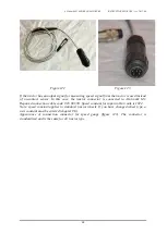
Page 68: ...In this case the tractor connector is connected to AG tronik M1 Required connection cable code 018 60 530 Speed constant for input in AG tronik is 1024 Note speed constant applies to standard tractor wheels If you have changed wheel type a new constant must be entered chapter 9 6 Appearance of connection connector for speed gauge figure 123 The connector is standardized and is the same for all tra...

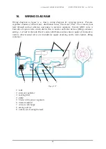
Page 69: ...egulator Central MAIN valve is basically an option valve which directs flow to nozzles and other devices filling container mixing or back in the tank Electric motor distribution valves ensure supply of chemicals to nozzles other manual valves are intended for supply of mixing nozzle tank cleaners filling container 2 9 1 5 4 3 6 7 8 Figure 122 1 tank 2 pressure regulator 3 sucking filter 4 pump 5 b...

Page 70: ...xternal part of the regulator and grease rotating and sliding parts Most appropriate agent is WD 40 or similar maintenance agents 3 During winter all water must be emptied out of the regulator the valves must be left open or keep the regulator in a warm place If you fill the sprayer during winter with antifreeze or agent against freezing of windows open valves on nozzles to prevent freezing in dea...

Reviews: