background image

5

FIGURE 2

FIGURE 3

2.  Assemble the two hitch braces to the inside of the hopper 

frame, one on each side, using two 1/4" x 1-1/2" hex 
bolts (A) and two 1/4" nylock nuts (D). 

DO NOT TIGHTEN 

yET.

 See figure 2.

3.  Remove the nut from the middle bolt in the crossover 

tube and shaft support plate. Leave the bolt in place. 
See figure 2.

4.  Assemble the hitch tube onto the middle bolt and secure 

it with the same nut you removed. 

DO NOT TIGHTEN 

yET.

 See figure 2.

IMPORTANT:

  The hitch tube must attach to the side of the 

crossover tube opposite the shaft support plate.

5.  Assemble the two hitch braces to the hitch tube using a 

1/4" x 1-1/2" hex bolt (A) and a 1/4" nylock nut(D). 

DO 

NOT TIGHTEN yET.

 See figure 2.

6. 

Tighten 

the nuts and bolts fastening the hitch braces 

to  the  hopper  frame  and  the  hitch  tube,  then  tighten 
the  middle  lock  nut  fastening  the  hitch  tube  to  the 
crossover tube. 

DO NOT COLLAPSE TUBES WHEN 

TIGHTENING.

(A) 1/4" x 1-1/2"
HEX BOLTS

(D) 1/4"
NYLOCK
NUTS

CROSSOVER
TUBE

HITCH BRACE

HITCH
TUBE

SHAFT
SUPPORT
PLATE

MIDDLE
NUT

MIDDLE BOLT

HITCH BRACE

7.  Select the end of the axle with no cross hole. Assemble 

a spacer (L), a 5/8" flat washer (G), a wheel (air valve 
facing out) and then another 5/8" flat washer (G) onto 
the axle. See figure 3.

8.  Install a hub cap (Q) by tapping it carefully onto the axle 

with a hammer. See figure 3.

(L) SPACER

(G) 5/8" DIA.
FLAT WASHER

(G) 5/8" DIA.
FLAT WASHER

(Q) HUB CAP

AIR VALVE

ENGLISH

FIGURE 4

9.  Select the end of the axle containing the cross hole. 

Assemble a spacer (L), a 5/8" flat washer (G), a wheel 
(air valve facing out) and then another 5/8" flat washer 
(G)  onto  the  axle.  Insert  the  5/32"  x  2"  cotter  pin  (I) 
through the wheel hub and the axle and then spread 
the ends of the pin. See figure 4.

10.  Install a hub cap (Q) by tapping it carefully onto the axle 

with a hammer. See figure 4.

(I) 5/32" x 2"
COTTER PIN

AIR VALVE

(L) SPACER

(G) 5/8" DIA.
FLAT WASHER

(Q) HUB CAP

Summary of Contents for 45-02114

Page 1: ...GRANDE PORT E REMORQUER owners manual MANUAL DEL USUARIO NOTICE D UTILISATION CAUTION Read Rules for Safe Operation and Instructions Carefully Model No Modelo No Mod le No 45 02114 ATTENTION Lire et...

Page 2: ...Flujo 5 Puntales 2 6 Barra de Control de Flujo 7 Ruedas 2 8 Tapa de la Tolva Paquete de Elementos de Ferreter a vea la p gina 3 CARTON CONTENTS Loose Parts in Carton CONTENIDO DE LA CAJA Partes Suelt...

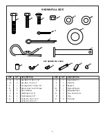
Page 3: ...ead E 4 Nylon Washer F 6 Flat Washer 5 16 G 4 Flat Washers 5 8 H 1 Cotter Pin 3 32 x 3 4 I 1 Cotter Pin 5 32 x 2 D C B A I J E K L M N O P NOT SHOWN FULL SIZE SHOWN FULL SIZE F H G Q ref qty descripti...

Page 4: ...ions for handling and applying the chemicals purchased for spreading Wear eye and hand protection when handling and when applying lawn or garden chemicals Never operate tractor and spreader attachment...

Page 5: ...ch tube to the crossover tube DO NOT COLLAPSE TUBES WHEN TIGHTENING A 1 4 x 1 1 2 HEX BOLTS D 1 4 NYLOCK NUTS CROSSOVER TUBE HITCH BRACE HITCH TUBE SHAFT SUPPORT PLATE MIDDLE NUT MIDDLE BOLT HITCH BRA...

Page 6: ...x 1 hex bolt B a nylon washer E and a 1 4 nylock nut D Tighten carefully The flow control link should not be loose but should pivot with no more than slight resistance See figure 6 FIGURE 6 15 Assemb...

Page 7: ...ADJUSTABLE STOP ENGLISH 21 Position the flow control mounting bracket figure 12 a Push on flow control arm until it locks in OFF position b Slide flow control mounting bracket along tube until closur...

Page 8: ...tractor 8 Iffertilizerisaccidentallydepositedtooheavilyinasmall area soak the area thoroughly with a garden hose or sprinkler to prevent burning of the lawn 9 To insure uniform coverage make each pas...

Page 9: ...See figure 14 5 Lightly apply automotive grease as needed to the sprocket and gear 6 Oil the nylon bushings on the vertical sprocket shaft and on the axle at least once a year or more often as needed...

Page 10: ...enprimera bajo yconel motorabajavelocidad yaumentegradualmentelavelocidad seg n lo permitan las condiciones Cuando arrastre el esparcidor de lanzado no conduzca demasiado cerca de quebradas o zanjas y...

Page 11: ...eydeltubodeengancheyaseg relosconelpasador de aleta J Vea la figura 5 14 Instale el eslab n de control de flujo O por el extremo del agujero peque o en el brazo de control de flujo usando un perno hex...

Page 12: ...diferentes materiales se muestran en el cuadro de aplicaci n en esta p gina 10 Cuandoapliquefertilizantesparacontroldehierbasomalezas aseg rese de que el patr n de lanzado no llegue a los rboles de v...

Page 13: ...e la rueda dentada y en el eje de las ruedas por lo menos una vez al a o o con m s frecuencia si es necesario 7 Aceite el cojinete de la rueda derecha engranaje libre por lo menos una vez al a o o con...

Page 14: ...personne sur l attelage de l pandeur Ne laissez jamais d enfants utiliser le tracteur ni la remorque et ne laissez aucun adulte utiliser le tracteur ni la remorque sans lui avoir fourni auparavant les...

Page 15: ...ez le support d attelage sur le dessus du tube d attelage en utilisant deux boulons hex de 1 4 x 1 po B et deux crous frein lastique D Voir l illustration 5 13 Ins rez la goupille d attelage K dans le...

Page 16: ...port e de l pandeur sera large 6 Veillez ce que le tracteur soit en train de rouler avant d ouvrir la plaque de debit 7 Assurez vousquelaplaquededebitestferm eavantd arreter ou d effectuer un tournan...

Page 17: ...eudegraissepourautomobilessurlacouronne et l engrenage si n cessaire 6 Huilez les fourrures en nylon de l arbre vertical de la couronne ainsi que l essieu au moins une fois par an ou plus souvent si n...

Page 18: ...23 43 22 21 20 21 22 19 18 4 D E 35 22 16 37 37 39 23 A A 37 15 27 26 28 3 19 36 34 9 46 9 7 9 40 16 14 17 37 24 22 9 E 9 29 5 4 9 35 B 6 38 44 47 48 48 8 42 40 9 D 45 11 48 29 40 38 49 25 B 1 39 10...

Page 19: ...Shaft Sprocket 26 04367 1 Spreader Plate Purchase common hardware locally the fastest way to purchase parts www speedepart com REF PART NO QTY DESCRIPTION 27 43850 1 Pin Spring 1 8 Dia x 5 8 28 44468...

Page 20: ...the Universal Copyright Convention and the Berne convention No part of this document may be reproduced or transmitted in any form or by any means electronic or mechanical including photocopying or re...

Reviews: