25
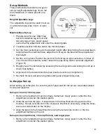
2. Attach the leg set with two side legs at the front and the centerline leg at the rear. Set
all three legs so the appropriate pipe size mark is aligned with the centerline-of-beam
marks beside each leg slot.
3. Slide the unit into pipe and rough level in the cross-axis direction using the cross-axis
level vial indicator on the display.
4. Align the beam to the forward manhole using the remote line adjust, or the line
adjustment buttons on the unit.
5. The beam should be projecting at pipe centerline. Allow the unit to self-level, then lay
pipe.
NOTE: If preferred, the 6 inch (150 mm) can be used for ALL in pipe set-ups as long as it is
remembered to reference the lower offset to the gravel and trench excavation depth. What is
important is that the beam elevation from the invert and the target centerline elevation from
the invert is the same.
Invert Set-up
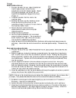
Position the legs the same as if setting up inside
the pipe. Place the laser in the invert and
complete the set-up as shown in the Manhole
Base Set-up in the previous section.
Open Cut Set-up
When using the height adjustable legs in an
open cut, a stable base such as a concrete
block, brick, or board must be placed in the cut
at the manhole center and marked. This is best
done when transferring elevation (see “Transfer
of Elevation” in Applications section).
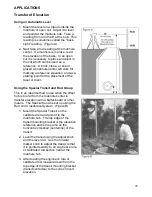
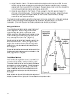
Place one of the blocks at manhole center. The
front leg will be positioned on this block 2 inches
(5 cm) in front of the center mark for critical high
accuracy, or on top of a centerline hub for most
applications. Place the other blocks, etc. so they provide support for the rear legs (Figure I).
Set up the unit for laying pipe as described in Manhole Base Set-up in the previous section.
Invert Peg Set-up (Open Cut)
This method is commonly used in open ditches. The cut should be excavated approximately
6 inches (150 mm) below invert elevation. (Figure I)
1. Place a stake at the invert elevation.
2. Prepare the laser for use: apply power, center the line adjust range, and enter the
desired grade. Attach the leg set with the centerline leg at the front and the two side
legs at the rear.
3. Set the front centerline leg for correct pipe size using the marks on the legs.
4. Place the laser in the trench with the single front leg on the stake (peg). Rest the rear
legs on blocks, bricks, or the ground.
5. Align the beam to the forward manhole.
6. Recheck for accurate grade settings and a level unit. Proceed to lay pipe.
NOTE: In open cut set-ups the optional long leg set is usually required.
Summary of Contents for GradeLight 3000
Page 1: ...GradeLight 3000 Pipe Laser ...
Page 4: ...3 Laser Overview ...
Page 38: ...37 ...
Page 39: ...38 ...
Page 40: ...39 Printed in USA AM1145 3 10 Specifications subject to change without notice ...


