Installation Note E8362-90016
11
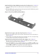
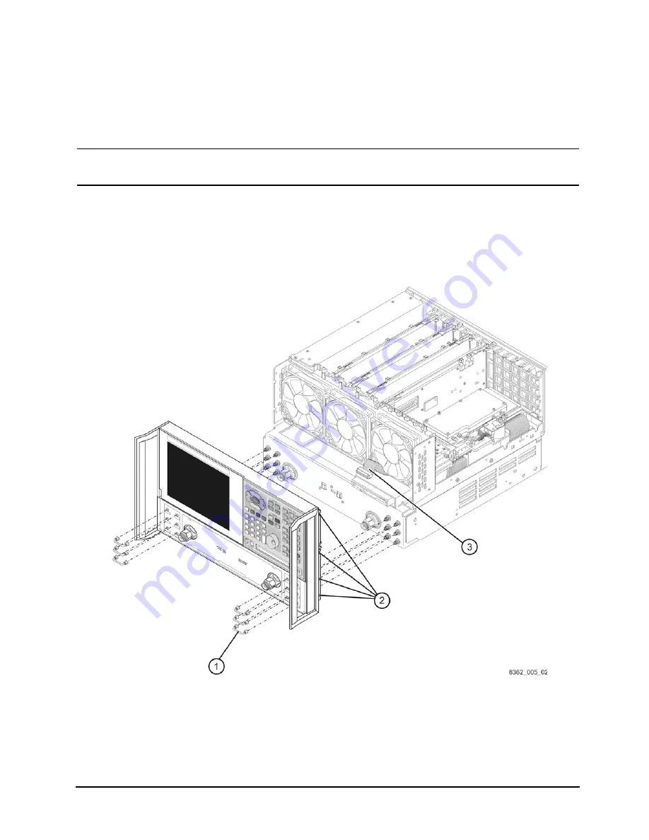
Step 4. Remove the Front Panel Assembly
1. Using a 5/16-inch wrench, remove the six front panel semirigid jumper cables (item
①
).
2. Using a T-10 TORX driver, remove the eight screws (item
②
) from the sides of the frame.
CAUTION
Before removing the front panel from the analyzer, lift and support the front of
the analyzer chassis.
3. Slide the front panel over the test port connectors.
4. Disconnect the front panel interface ribbon cable (item
③
). The front panel is now free
from the analyzer.
Figure 4
Front Panel Assembly Removal

