


78
Chapter 2
Programming Fundamentals
Using the Instrument Status Registers
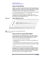
To query the status byte register, send the command
*STB?
The
response will be the decimal sum of the bits which are set to 1. For
example, if bit number 7 and bit number 3 are set to 1, the decimal sum
of the 2 bits is 128 plus 8. So the decimal value 136 is returned.
Bit
Description
0, 1
These bits are always set to 0.
2
A 1 in this bit position indicates that the SCPI error queue is not empty. The SCPI error
queue contains at least one error message.
3
A 1 in this bit position indicates that the data questionable summary bit has been set.
The data questionable event register can then be read to determine the specific condition
that caused this bit to be set.
4
A 1 in this bit position indicates that the instrument has data ready in the output queue.
There are no lower status groups that provide input to this bit.
5
A 1 in this bit position indicates that the standard event summary bit has been set. The
standard event status register can then be read to determine the specific event that
caused this bit to be set.
6
A 1 in this bit position indicates that the instrument has at least one reason to report a
status change. This bit is also called the master summary status bit (MSS).
7
A 1 in this bit position indicates that the standard operation summary bit has been set.
The standard operation event register can then be read to determine the specific
condition that caused this bit to be set.
Summary of Contents for E4406A VSA Series
Page 4: ...4 ...
Page 59: ...59 2 Programming Fundamentals ...
Page 124: ...124 Chapter2 Programming Fundamentals Using the LAN to Control the Analyzer ...
Page 125: ...125 3 Programming Examples ...
Page 164: ...164 Chapter3 Programming Examples Using Java Programming Over Socket LAN ...
Page 165: ...165 4 Programming Command Cross References ...
Page 379: ...379 6 Error Messages ...
Page 412: ...412 Chapter6 Error Messages Error Message Descriptions ...