


E2730A VXI RF TUNER
OPERATION
3-19
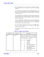
During normal operation the tuner LO status is continually monitored.
The error status bits are set to indicate the results of the monitoring
operations.
The tuner includes three command queries for determining hardware error
status. Each of the commands returns a bit mapped value between 0 and
65535, where each bit indicates the hardware status of a particular
subsystem of the tuner.
The Current Device Error (CDE) status query returns the current status of
the LO subsystems. This is not a latched register. If an LO went unlocked
and then re-locked prior to the CDE? query, there would be no evidence of
this error in the response.
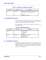
The Device Dependent Error (DDE) status query returns a latched history
of any errors that have occurred since the last read of this register.
Reading the DDE clears any latched errors. If the error condition still
exists, the bit will be immediately reactivated.
The *TST command responds with same data as the DDE? query.
However, the *TST status query does not clear the latched device
dependent error status register.
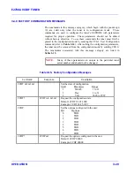
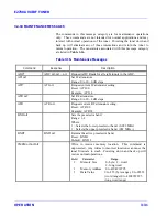
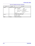
The mnemonics associated with this message category are listed in
Table 3-11
.
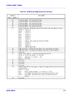
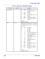
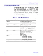
Table 3-11. Hardware Error Messages
Command
Response
Description
CDE?
CDE nr1
Request the current device Error Register
contents. Reading this register does not affect
its contents. This is a bit mapped response
where 0 = (Okay) and 1 = (Fault).
Bit
Value
Description
0
1
Not Used
1
2
Not Used
2
4
Not Used
3
8
Not Used
4
16
FXE, FLEX Bootload failure
5
32
1LO, 1st LO unlocked
6
64
2LOT, 2nd LO Translation
Loop unlocked
7
128
2LOR, 2nd LO Resolution
Loop unlocked
Summary of Contents for E2730A
Page 5: ...E2730A VXI RF TUNER iv LIST OF EFFECTIVE PAGES THIS PAGE INTENTIONALLY LEFT BLANK ...
Page 7: ...E2730A VXI RF TUNER vi REVISION RECORD THIS PAGE INTENTIONALLY LEFT BLANK ...
Page 12: ...1 i SECTION 1 GENERAL DESCRIPTION ...
Page 13: ...1 ii THIS PAGE INTENTIONALLY LEFT BLANK ...
Page 18: ...2 i SECTION 2 INSTALLATION ...
Page 19: ...2 ii THIS PAGE INTENTIONALLY LEFT BLANK ...
Page 32: ...3 i SECTION 3 OPERATION ...
Page 33: ...3 ii THIS PAGE INTENTIONALLY LEFT BLANK ...
Page 66: ...4 i SECTION 4 REPLACEMENT PARTS LIST ...
Page 67: ...4 ii THIS PAGE INTENTIONALLY LEFT BLANK ...
Page 71: ...E2730A VXI RF TUNER 4 4 REPLACEMENT PARTS LIST NOTES ...
Page 72: ...FP i FOLDOUTS ...


