


E2730A VXI RF TUNER
INSTALLATION
2-1
SECTION 2
INSTALLATION
2.1 UNPACKING AND INSPECTION
The E2730A and its accessories are shipped cushioned between molded-in-
place expanded plastic pads in a double-walled carton. After unpacking the
equipment, retain the shipping container and packing material until the
equipment has been thoroughly inspected and it is ensured that reshipment
is not necessary. Perform the following initial inspection:
1.
Carefully inspect the outside of the shipping container for
discoloring, stains, charring, or other signs of exposure to excessive
heat, moisture or liquid chemicals. Check for any physical damage
to the shipping container such as dents, snags, rips, crushed areas, or
similar signs of excessive shock or careless handling.
2.
Remove all equipment and accessories from the shipping container.
If any items are missing, contact your Agilent Technologies
Customer Engineer.
3.
Carefully inspect the equipment looking for dents, scratches,
damaged or loose controls, indicators, or connectors, or any other
signs of physical abuse or careless handling.
If damage is found, forward an immediate request to the delivering carrier
to perform an inspection and prepare a concealed-damage report. Do not
destroy any packing material until it has been examined by an agent of the
carrier. Concurrently, report the nature and extent of damage to your
Customer Engineeer through your local Agilent Technologies Service
Center. Under U.S. shipping regulations, damage for claims must be
collected by the consignee; do not return the equipment to Agilent
Technologies until a claim for damages has been established.
2.2 CONNECTOR SIGNALS
The following paragraphs describe the input and output signals provided at
the tuner’s front panel connectors. The signals at the rear panel VXIbus
P1/P2 connectors are described in the VXIbus System Specification. For
convenience, their pin assignments are included here.
Table 2-1
lists all
of the E2730A’s external connectors, their reference designations and
basic functions.
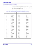
Table 2-2
lists the mating connector types, the associated
part numbers and the manufacturer’s CAGE Code (if applicable).
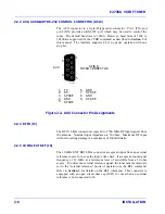
Figure 2-1
shows the location of the connectors.
Summary of Contents for E2730A
Page 5: ...E2730A VXI RF TUNER iv LIST OF EFFECTIVE PAGES THIS PAGE INTENTIONALLY LEFT BLANK ...
Page 7: ...E2730A VXI RF TUNER vi REVISION RECORD THIS PAGE INTENTIONALLY LEFT BLANK ...
Page 12: ...1 i SECTION 1 GENERAL DESCRIPTION ...
Page 13: ...1 ii THIS PAGE INTENTIONALLY LEFT BLANK ...
Page 18: ...2 i SECTION 2 INSTALLATION ...
Page 19: ...2 ii THIS PAGE INTENTIONALLY LEFT BLANK ...
Page 32: ...3 i SECTION 3 OPERATION ...
Page 33: ...3 ii THIS PAGE INTENTIONALLY LEFT BLANK ...
Page 66: ...4 i SECTION 4 REPLACEMENT PARTS LIST ...
Page 67: ...4 ii THIS PAGE INTENTIONALLY LEFT BLANK ...
Page 71: ...E2730A VXI RF TUNER 4 4 REPLACEMENT PARTS LIST NOTES ...
Page 72: ...FP i FOLDOUTS ...


