


E2730A VXI RF TUNER
2-6
INSTALLATION
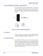
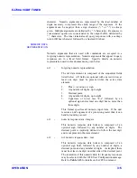
2.2.3 AUX, AUXILIARY RS-232 CONTROL CONNECTOR (A5J2)
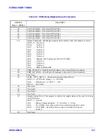
The AUX connector is a 9-pin D-type microconnector. Pin 1 (TX) and
pin 2 (RX) provide an RS-232C port which may be used to control the
tuner. The default baud rate is 19200. However, baud rates of 1200 to
38400 are supported via the #CBR command as described in
Section 3
of
this manual. The interface supports 8 bit, no parity operation with one
stop bit.
AUX
6
1
5
9-PIN D,
MICROCONNECTOR
99-0040
9
1.
2.
3.
4.
5.
TX
RX
SPARE
GND
SPARE
GND
SPARE
GND
SPARE
6.
7.
8.
9.
Figure 2-2. AUX Connector Pin Assignments
2.2.4 RF IN (J2)
The RF IN SMA connector accepts 20 to 2700 MHz RF input signals from
the antenna. Nominal input impedance is 50 ohms. Maximum RF input
without incurring damage is a maximum of 100 milliwatts.
2.2.5 10 MHz EXT REF (J8)
The 10 MHz EXT REF SMA connector accepts an input from an external
reference source for use as the tuner’s time base. It accepts an input signal
frequency of 10 MHz, at a minimum level of zero dBm from a 50 ohm
source. To utilize the external reference signal, the tuner must be remotely
set to the “external reference” mode of operation via the REF command.
Refer to
Section 3
for details on the REF command. This connector is
equipped with an open circuit dust cap (MP1) for use when an external
reference is not connected to J8.
Summary of Contents for E2730A
Page 5: ...E2730A VXI RF TUNER iv LIST OF EFFECTIVE PAGES THIS PAGE INTENTIONALLY LEFT BLANK ...
Page 7: ...E2730A VXI RF TUNER vi REVISION RECORD THIS PAGE INTENTIONALLY LEFT BLANK ...
Page 12: ...1 i SECTION 1 GENERAL DESCRIPTION ...
Page 13: ...1 ii THIS PAGE INTENTIONALLY LEFT BLANK ...
Page 18: ...2 i SECTION 2 INSTALLATION ...
Page 19: ...2 ii THIS PAGE INTENTIONALLY LEFT BLANK ...
Page 32: ...3 i SECTION 3 OPERATION ...
Page 33: ...3 ii THIS PAGE INTENTIONALLY LEFT BLANK ...
Page 66: ...4 i SECTION 4 REPLACEMENT PARTS LIST ...
Page 67: ...4 ii THIS PAGE INTENTIONALLY LEFT BLANK ...
Page 71: ...E2730A VXI RF TUNER 4 4 REPLACEMENT PARTS LIST NOTES ...
Page 72: ...FP i FOLDOUTS ...


