background image

USER INTERFACE 

12


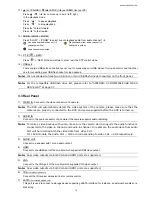
2.1.2 Channel Status 

Note: 

Certain icons are for selected models only.


Live audio on 

Audio off 


Audio playback on 

Audio playback off 


Recording 

PTZ control 

Motion event 

Alarm event 

  PIR event 


Virtual fence event 

  One way pass event 

  Scene Change event 

2.1.3 Record-related Icons 

1) Manual Recording 

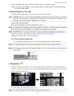
By defaults, manual recording is on ( ) when the DVR is powered on and a hard disk is installed. 

2) Event Recording 

The event icons, 

 / 

 / 

 / 

 / 

 / 

, show on the channel status bar when their respective 

events occur and the related record function is on. 

3) Timer Recording 

When timer recording is on, you will see “

” on the screen. 

4) HDD Overwritten 

Be defaults, the HDD overwritten function is set to ON, and “

” will be shown on the screen. 

Note: 

To disable this function, right click to display the main menu in the live view, and go to “ ” 
(ADVANCED CONFIG.) 

 “RECORD” 

 “OVERWRITE”.


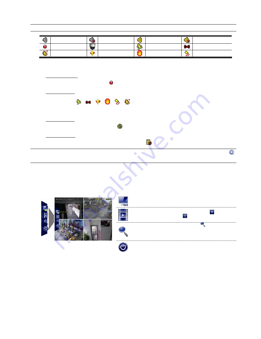
2.3 Quick Menu Bar 

Move to the arrow mark to extend the quick menu bar and show the five functions as follows: 

Quick Menu: Open 


Click to show the channel switch panel and select the channel you 
want.  


Click to display the playback control panel, and click 

  to play the 

latest recorded video clip, or click 

  to enter the search list. 


Switch to the channel you want first, and click 

  to enter the zoom-in 

mode. In this mode, click and drag the red frame on the bottom left of 
the screen to move to the place you want to see. To exit this mode, 
click 


Click to show the power off panel to either halt or reboot the system. 


Summary of Contents for VC-SYS-HT1603

Page 1: ...START 1080P Video Recording Please read instructions thoroughly before operation and retain it for future reference For the actual display operation please refer to your DVR in hand Complete user manual download www surveillance download com user t204 swf ...

Page 2: ......

Page 3: ...device pursuant to Part 15 of the FCC Rules These limits are designed to provide reasonable protection against harmful interference when the equipment is operated in a commercial environment This equipment generates uses and can radiate radio frequency energy and if not installed and used in accordance with the instruction manual may cause harmful interference to radio communications Operation of ...

Page 4: ... LICENSING MAY BE OBTAINED FROM MPEG LA LLC SEE HTTP WWW MPEGLA COM GPL Licensing This product contains codes which are developed by Third Party Companies and which are subject to the GNU General Public License GPL or the GNU Lesser Public License LGPL The GPL Code used in this product is released without warranty and is subject to the copyright of the corresponding author Further source codes whi...

Page 5: ... 1 1 DVR Status 11 2 1 2 Channel Status 12 2 1 3 Record related Icons 12 2 3 Quick Menu Bar 12 2 4 Main Menu 13 3 HARDWARE OVERVIEW 15 3 1 Package Content 15 3 2 Front Panel 15 3 3 Rear Panel 16 4 FREQUENTLY USED FUNCTIONS 19 4 1 Key Lock Unlock 19 4 2 User Level Creation 19 4 3 PTZ Control 20 4 4 Playback 22 4 4 1 Playback Control 22 4 4 2 Event Search 22 4 4 3 Audio Playback 23 4 5 Video Backup ...

Page 6: ...quisites 33 A2 2 Where to download 33 APPENDIX 3 SET PUSH VIDEO 34 A3 1 Prerequisite 34 A3 2 Enable Push Video 35 A3 2 1 From iOS Mobile Device iPhone iPad 35 A3 2 2 From Android Mobile Device 36 APPENDIX 4 COMPATIBLE USB FLASH DRIVE LIST 37 APPENDIX 5 COMPATIBLE SATA HDD LIST 38 APPENDIX 6 MAIN MENU STRUCTURE 39 ...

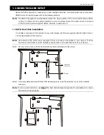
Page 7: ...sk is necessary for the recorder to save video footage and firmware upgrade might be failed if there s no hard disk installed in this recorder Note Here takes a 8CH model as an example of how to connect a hard disk to your device To know how many hard disks could be installed please refer to the specifications of your device Step1 Remove the top cover and find the hard disk connector and bracket i...

Page 8: ...era with indicated power supply and make sure it s power supplied 1 2 2 Speed Dome Camera The following description is taking our brand s speed dome camera as an example Note The RS485 wiring is not needed when your DVR and speed dome camera are both our HD CCTV series If yes please go to STEP 5 directly for PTZ camera setting Note Speed dome camera connection for non HD CCTV series is available o...

Page 9: ...2400 RECORD DEVICES DCCS IVS NOTIFY EXIT 1 3 External Device Connection Some DVR models support external device connection with RS485 and alarm I O ports allowing users to connect control devices such as a keyboard controller or connect alarm devices such as a magnetic contact or buzzer Check the user manual of your external device to know which pin s should be used and connect it to the correspon...

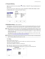
Page 10: ... in APPENDIX 8 DVR BATTERY REPLACEMENT in the user manual Right click to enter the DVR password with the password keypad The default administrator password is admin The status will be changed from key lock to unlock Then right click to show the main menu and select QUICK START TIME SETUP to set the date time QUICK START GENERAL DATE 2009 NOV 17 TIME SETUP TIME 15 35 53 DAYLIGHT NTP SERVER pool ntp...

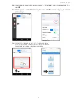
Page 11: ...a allowance approx 2185 minutes for free When 2GB is up the network transmission will be down to 1 FPS To restore the fluency of live view users need to subscribe a data plan from EagleEyes or configure the network settings by themselves To connect this recorder to the Internet without using EaZy Networking get the network setup manual from www surveillance download com user t204 swf Note Data all...

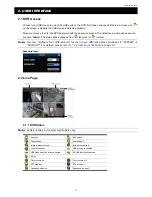
Page 12: ...s book Then click Step4 Click Login in the section of Cloud and register an account for Cloud Service If you ve got an account please just log in Step5 Go back to the address book and click to add a new device There are two methods to add new devices EaZy and Manual Select EaZy and choose the DVR icon to continue ...

Page 13: ... the settings and see if this device is added successfully to the address book as a cloud device When the device is added successfully to the cloud service the DVR will also prompt a message indicating the device is added successfully Step8 Click the newly added device and see if you could access successfully 1 8 2 Checking Remaining Data Allowance To know how much data allowance is left Step1 Log...

Page 14: ...ailed because it is still restricted to the maximum online user setup of the device i e To allow other account to access your cloud device Step1 Log into the cloud service Step2 Select Buddy to go to the buddy sharing page Then choose the cloud device you want to share and click Share to Buddy Step3 Enter the cloud account or the E mail registered by the account and select Add ...

Page 15: ...tep5 Specify the access permission of the specified account which account s data allowance should be consumed after access successfully and how long the account is allowed to stay after access successfully Step6 Check again the configurations you made for the account to which you want to share your cloud device and select Share to confirm ...

Page 16: ...CONNECTION AND SETUP 10 ...

Page 17: ...m key lock to unlock Note You may configure four different user levels to have different access privileges in SYSTEM ACCOUNT For details please refer to 4 2 User Level Creation at page 19 Password Input 2 2 Live Page 2 1 1 DVR Status Note Certain icons are for selected models only Key lock Key unlock Overwrite on Overwrite off Internet disconnected Internet connected Local connection USB mouse con...

Page 18: ...ritten Be defaults the HDD overwritten function is set to ON and will be shown on the screen Note To disable this function right click to display the main menu in the live view and go to ADVANCED CONFIG RECORD OVERWRITE 2 3 Quick Menu Bar Move to the arrow mark to extend the quick menu bar and show the five functions as follows Quick Menu Open Click to show the channel switch panel and select the ...

Page 19: ...atus display image settings and date time SYSTEM Click to set the system configurations EVENT INFORMATION Click to enter the event search menu ADVANCED CONFIG Click to set CAMERA DETECTION ALERT NETWORK DISPLAY RECORD DEVICES DCCS IVS and NOTIFY SCHEDULE SETTING Click to set timer for record motion detection alarm in and out Push Video and buzzer For selected models only ...

Page 20: ...USER INTERFACE 14 ...

Page 21: ...select the channel to display 3 Press to show the 4 channel display mode 4 SEQ Press to display each channel in full screen one by one starting from CH1 When the last channel is displayed it will repeat from CH1 again To exit this mode press SEQ again 5 SLOW In the playback mode press to show slow playback 6 ZOOM Press to enlarge the picture of selected channel in the FRAME or FIELD recording mode...

Page 22: ...ically detect the video system of the camera please make sure that the cameras are properly connected to the DVR and power supplied before the DVR is turned on 2 AUDIO IN Connect to the audio connector of a camera if the camera supports audio recording Note To make a video backup with audio make sure the camera which supports the audio function is connected to the video in channel and audio in cha...

Page 23: ...et default on your disk array and try again 8 EXTERNAL I O For selected models only This port is used to connect external devices such as speed dome cameras or external alarm etc 9 LAN Connect to Internet by LAN cable 10 DC IN Connect to the supplied adapter 11 VIDEO OUT Connect to a CRT monitor for main monitor output 12 Power Switch For selected models only Switch to to turn on the power and to ...

Page 24: ...HARDWARE OVERVIEW 18 ...

Page 25: ...l Creation at page 19 4 2 User Level Creation Note This function is available only for SUPERVISOR To create different user account for different access privilege click SYSTEM and select ACCOUNT to enter USER LIST SYSTEM ACCOUNT USER LIST TOOLS USER NAME LEVEL SYSTEM INFO admin SUPERVISOR BACKUP DATA power POWER USER BACKUP LOG normal NORMAL REGULAR REPORT guest GUEST EXIT ADD EDIT DEL Different us...

Page 26: ...t only show specific icons for focal length and focus adjustment For details please refer to its own user manual In the full view In the split view click the channel you want to switch to the full screen mode and click to show the PTZ control panel Camera Menu Click to enter the camera main menu For details about each camera menu please refer to its own user manual Enter Click to confirm your sele...

Page 27: ... length the camera will use the parameters as the ones for Auto Focus Auto Focus Click to automatically adjust the focus of the camera In the split view Click on the channel status bar to display the panel as follows Up Down Left Right Click to move your selection up down left right or change settings Digital zoom in out Click to zoom in out the camera image digitally Focus near far Click to adjus...

Page 28: ...ick twice to get 8X speed etc and the maximum speed is 32X Fast Rewind Increase the speed for fast rewind Click once to get 4X speed rewind and click twice to get 8X speed etc and the maximum speed is 32X Play Pause Click to play the latest recorded video clip immediately and click again to pause In the pause mode click once to get one frame forward and click to get one frame rewind Stop Click to ...

Page 29: ...orded data saved in the hard disk To copy video data for video backup click SYSTEM and select BACKUP DATA SYSTEM ACCOUNT START DATE 2009 NOV 19 TOOLS START TIME 08 30 21 SYSTEM INFO END DATE 2009 NOV 19 BACKUP DATA END TIME 17 59 29 BACKUP LOG CHANNEL 3 SELECTED REGULAR REPORT ALL CH1 CH2 CH3 CH4 CH5 HARD DISK ALL HDD OUTPUT FILE FORMAT AVI TARGET DEVICE USB DEVICE BACKUP SUBMIT REQUIRE SIZE 554MB...

Page 30: ...ER EXE in the USB flash drive and double click it to install Note PLAYER EXE can also be downloaded from www surveillance download com user t204 swf Step3 Run the program VideoPlayer and browse to where you save the recorded data Step4 Select the file you want to start video playback 4 6 1 Convert the file format to AVI To convert the video file format to AVI click AVI from the playback panel to s...

Page 31: ...ormat is ipaddress portnum For example for the IP address 60 121 46 236 and port No 888 please key in http 60 121 46 236 888 into the URL address box and press Enter Step 2 Enter the user name and password and click OK You will see a similar screen as the following when the login information is correct Note The default user name and password for remote access are both admin Icon Description Click ...

Page 32: ...to enable local desktop display remotely An individual window will pop up to show the local view All operations available at the local side could be done independently and remotely in this window Click to switch the display to full screen Event Search Playback Increase the speed for fast rewind Click once to get 4X speed rewind and click twice to get 8X speed etc and the maximum speed is 32X Incre...

Page 33: ...REMOTE OPERATION 27 5 1 1 IVS Statistics Note This function is for selected models only ...

Page 34: ...oint numbering to which you want your camera to move Click to adjust the focus of the image Click to zoom in out the image Click to zoom in on the image to the largest zoom out on the image to its original size Click to start auto tracking when your speed dome camera supports this function Click to take a snapshot of the current view and save it to the specified path in your PC set in General Clic...

Page 35: ...ur mobile platform is iOS or Android Mobile Internet services are subscribed and available to use for your mobile device Note You might be charged for Internet access via the wireless or 3G network For the Internet access rate details please check with your local network operator or service provider You have noted down the IP address port number user name and password used to access your network c...

Page 36: ...xamine if the information you entered is correct The device type will be detected properly Step4 Optional Configure the settings in the OPTIONAL column as needed Step5 Click Save to return to the address book Enable Guard to receive Push Video Push Status Step6 Click on the item you just added in the address book to access and check the live view ...

Page 37: ...or an alarm event Push Video Note This function is for selected models only A1 1 Alarm Sensor Connection Connect the alarm sensor such as magnetic contacts to the alarm in port on the DVR rear panel Alarm in 1 corresponds to video channel 1 alarm in 2 corresponds to video channel 2 and so on Note The voltage restriction for alarm in device connection is under DC24V 1A ...

Page 38: ... to ADVANCED CONFIG NOTIFY In PUSH VIDEO select the alarm device you want and configure the alarm type ADVANCED CONFIG CANERA PUSH VIDEO PUSH STATUS MESSAGE MAIL VIDEO MAIL VIDEO FTP DETECTION RESET ALL GUARD CONNECTION SUBMIT ALERT GUARD TRIGGER BY ALARM IN 1 NETWORK CH01 ALARM OFF INTERNAL ALARM CH1 DISPLAY CH02 ALARM OFF CH2 RECORD CH03 ALARM N O office DEVICES CH04 ALARM OFF CH4 DCCS IVS NOTIF...

Page 39: ...atform is iOS or Android Mobile Internet services are subscribed and available to use for your mobile phone Note You might be charged for Internet access via wireless or 3G networks For the Internet access rate details please check with your local network operator or service provider You have noted down the IP address port number user name and password used to access your network camera from Inter...

Page 40: ...e checked the following You have an iOS or Android mobile device with our self developed program EagleEyes installed For details please refer to the previous chapter An external alarm device is connected to the external I O ports on the rear panel Make sure a camera is also connected to record for alarm occurrences To know which video channel corresponds to which alarm pin please refer to APPENDIX...

Page 41: ... Select EagleEyes and make sure the notification is set to on Step2 Open EagleEyes and switch Guard to ON You ll receive the message indicating that Push Video is on Step3 Return to the main page or standby page of iPhone iPad You ll receive event notifications when there s an alarm event Follow the on screen instruction to immediately play the recorded clip ...

Page 42: ...APPENDIX 3 SET PUSH VIDEO 36 A3 2 2 From Android Mobile Device In the address book switch Guard from OFF to ON ...

Page 43: ...at the USB flash drive as FAT32 Note You can backup up to 2GB video data for one time USB backup To backup more data please set the time channel s you want and start USB backup again MANUFACTURER MODEL CAPACITY Transcend JFV35 4GB JFV30 8GB Kingston DataTraveler 1GB PQI U172P 4GB Apacer AH320 2GB AH320A 8GB AH220 1GB AH320 4GB A data RB 18 1GB Sandisk Cruzer Micro 2GB Cruzer Micro 4GB Cruzer4 pk 2...

Page 44: ...500G ST2000VX004 2TB Pipeline HD ST1000VM002 1TB ST3000VM002 3TB Pipeline HD ST1000VM002 1TB ST3000VX004 3TB ST31000525SV 1TB ST3000VX000 3TB ST31000340AS 1TB ST4000VM000 4TB ST1000VX002 1TB ST4000VX002 4TB ST2000VX000 2TB WD MODEL CAPACITY MODEL CAPACITY WD10PURX 1TB WD30PURX 3TB WD20PURX 2TB WD30EURX 3TB WD20EURS 2TB WD30EFRX 3TB WD20EURX 2TB WD40PURX 4TB WD20EFRX 2TB WD40EURX 4TB WD2002FAEX 2TB...

Page 45: ...IG RESTORE CONFIG SYSTEM INFO BAUD RATE HOST ID R E T R AUTO KEY LOCK S CLEAR HDD RESET DEFAULT REMOTE CONTROL ID SERIAL TYPE VIDEO FORMAT VERSION BACKUP DATA BACKUP LOG REGULAR REPORT EVENT INFORMATION QUICK SEARCH EVENT SEARCH HDD INFO EVENT LOG ADVANCED CONFIG CAMERA BRIGHTNESS CONTRAST SATURATION HUE COV REC TIME STAMP DISPLAY CHANNEL TITLE REC AUDIO DETECTION LS SS TS MOTION ALARM AREA ALERT ...

Page 46: ... DISPLAY OUTPUT COVERT UNLOCK IN SUPERVISOR MODE RECORD MANUAL RECORD EVENT RECORD TIMER RECORD PRE ALARM RECORD OVERWRITE KEEP DATA LIMIT DAYS RECORD CONFIG SUBSTREAM RESOLUTION DEVICES DCCS IVS NOTIFY PUSH VIDEO PUSH STATUS MESSAGE MAIL VIDEO MAIL VIDEO FTP SCHEDULE SETTING RECORD DETECTION ALARM IN ALARM OUT PUSH VIDEO BUZZER For selected models only ...

Reviews: