Agena BIOSCIENCE MassARRAY Nanodispenser RS1000 User Manual Download Page 93

Chapter 4  Maintenance Procedures

91

USG-CUS-059 Rev05

MassARRAY® Nanodispenser RS1000 v2.1 User Guide

For Research Use Only. Not for use in diagnostic procedures.

4.4  Daily maintenance

These maintenance procedures should be performed each day before starting 
dispensing:

Clean the pins (below)

Drain and fill the ultrasonic wash supply bottle, page 94

Flush the calibrant reservoir, page 97

Fill the supply tank, page 99

Drain the waste tank, page 102

Clean the pins 

Before dispensing to SpectroCHIP Arrays, the pins must be cleaned by soaking the pins 
in 100% ethanol. Pin cleaning is usually required only once at the beginning of each day 
of use. The cleaning process takes approximately 30 minutes.

To clean the pins:

WARNING

!

WARNING!  

You will be handling ethanol in this procedure. For safe handling procedures, refer 

to the MSDS provided by your ethanol supplier. At a minimum: 1) wear protective clothing 

(laboratory gloves, eye protection, and laboratory coat), 2) have adequate laboratory ventilation, 

3) keep away from ignition sources, 4) and have proper fire extinguishing devices/solutions readily 

accessible.

1.

Go to the Maintenance screen (tap the Back button 

 on any screen and tap the 

MAINTENANCE

 button 

on the Main Menu).

2.

Tap 

SONICATOR SOLUTION Drain 

on the Maintenance screen 

(Figure 4.2)

.

The ultrasonic wash begins draining and an on-screen message displays the time 
remaining for the operation. Wait for draining to finish.

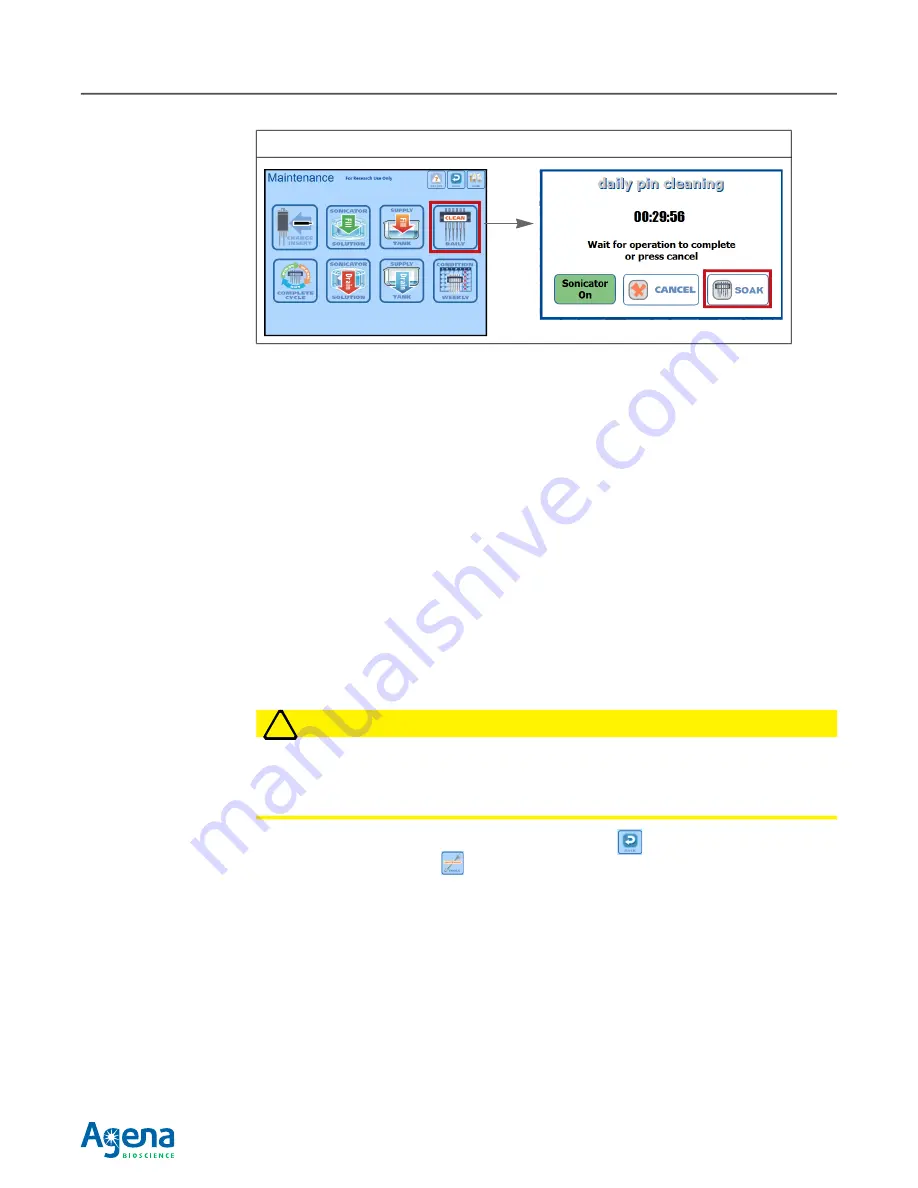
Figure 4.1   Starting the Pin Soak

Summary of Contents for MassARRAY Nanodispenser RS1000

Page 1: ...For Research Use Only Not for Use in Diagnostic Procedures MassARRAY Nanodispenser RS1000 USER GUIDE v2 1...

Page 2: ...7 501 251 7 888 127 7 917 301 8 003 317 8 315 805 8 349 566 9 249 456 9 310 378 9 394 565 9 669 376 and 9 896 724 and patents pending including but not limited to US20130017960 and foreign counterpart...

Page 3: ...checks 28 Setting up the dispensing run 30 Microtiter plate checks 39 Setting up the instrument deck 43 Starting the dispensing run 46 Dispensing run activities 49 Clearing the instrument deck 54 Acc...

Page 4: ...x B Manually Adjusting Dispense Speed 131 Appendix C External Tanks 135 External tanks vs internal tanks 135 Setting up an external supply tank 136 Setting up an external waste tank 138 Manually primi...

Page 5: ...nalyzer The Nanodispenser RS1000 supports all Agena Bioscience genetic analysis applications This user guide provides instructions for using the Nanodispenser RS1000 version 2 1 For instructions for u...

Page 6: ...uses computer controlled robotics to dispense nanoliter volumes of fluid from microtiter plates onto SpectroCHIP Arrays There are three versions of the instrument Table 1 2 Table 1 2 Differences Betw...

Page 7: ...omatic dispensing from a 384 well microtiter plate to a 384 SpectroCHIP Array Manual dispensing from a single well of a 384 well microtiter plate to a single pad on a 384 SpectroCHIP Array using the 1...

Page 8: ...nstrument Front Stop Button Immediately stops motion Touchscreen Controls the instrument Figure 1 3 Instrument Back Power Switch and Ports For more information about these ports see External ports pag...

Page 9: ...can also be used to connect external supply tank Warning The water from the waste ports may contain ethanol and residual DNA sample It must be disposed of properly according to local regulations Vac W...

Page 10: ...e pin array used to load and dispense liquid allows up and down movement X Axis Transport Allows side to side movement of pin array assembly Y Axis Transport Allows front to back movement of pin array...

Page 11: ...springs will assist lifting the door The door remains in the open position until you close it The safety interlock message is displayed while the door is open Figure 1 9 To close the main door grasp...

Page 12: ...e front access panel disengages the safety interlock and aborts a dispensing run in progress To open the front access panel 1 Open the main door See page 9 for more details NOTE The main door must be...

Page 13: ...he access panel lightly and press the brackets up to disengage them from the locked position 2 Lower the access panel closed CAUTION Be careful not to pinch fingers underneath the panel as you close i...

Page 14: ...not currently used It is reserved for future expansion Instrument specifications Table 1 4 Nanodispenser RS1000 Dimensions and Weight Table 1 5 Nanodispenser RS1000 Power Supply and Consumption Chara...

Page 15: ...ry Kit Plate centrifuge Min RCF 3200 x g min speed 4000 rpm Plate tube rotator 360 rotation with standard rotisserie Resin dimple plate and scraper Supplied with Agena Bioscience MassARRAY System Etha...

Page 16: ...NG A warning describes a situation that could cause personal injury damage to the instrument or pose environmental concerns WARNING WARNING Use the Nanodispenser RS1000 as specified by Agena Bioscienc...

Page 17: ...gered the run is aborted Even if a run is paused pressing the Stop button opening the main door or opening the front access panel will abort the run WARNING WARNING Do not attempt to override or circu...

Page 18: ...ate of analyte There should be enough analyte remaining in the wells for another transfer However you should use a new SpectroCHIP Array Personal protection You must wear laboratory gloves a laborator...

Page 19: ...not attempt to lift the instrument by yourself At least two people are required to lift the instrument Disconnect the instrument from its power supply before attempting to move it The instrument shou...

Page 20: ...r Desk orderdesk europe AgenaBio com Email support europe AgenaBio com ASIA PACIFIC Agena Bioscience Inc Ground Floor 27 Jeays Street Bowen Hills QLD 4006 Australia Phone 61 7 3088 1600 Fax 61 7 3088...

Page 21: ...ng Workflow Step See Page 1 Desalt the analyte 21 2 Turn on the Nanodispenser RS1000 and log on 22 3 Pre run checks Confirm that the daily maintenance procedures have been completed 91 Check the suppl...

Page 22: ...king the pins Example dispensing cycle Figure 2 1 shows an example dispensing cycle and deck setup with a single microtiter plate and SpectroCHIP Array on the deck The cycle step 1 through step 6 is r...

Page 23: ...5 Seal the plate and centrifuge at 3200 x g for 1 minute 6 To add dried Clean Resin to each well a Gently invert the sample plate on top of the dimple plate making sure that the plate wells are aligne...

Page 24: ...casionally add water as needed to keep resin completely submerged and store at room temperature STOPPING POINT If not proceeding directly to the next step the reaction plate should be sealed and store...

Page 25: ...n the Login screen 2 In the keyboard that appears type your user name and tap enter NOTE NOTE To cancel the keyboard tap the in the upper right corner 3 On the Login screen tap the password box 4 In t...

Page 26: ...goes dark if there is no instrument activity for 60 minutes Tap the screen to log on enter your user name and password and unlock the screen Shutting down the instrument NOTE NOTE Tap BACK on any scre...

Page 27: ...usually recommended that you save the configuration file so that the instrument uses the last configuration parameters If you are unsure whether parameter changes were made or if unintentional changes...

Page 28: ...n name Add delete or change user information Only the administrator can add delete or change user information NOTE NOTE Log off the instrument when you finish managing users It is recommended that you...

Page 29: ...ious user by tapping LOG OFF on the main menu The User Setup screen appears 2 To add a user a Tap the ADD USER button in the User Setup screen b In the dialog box that appears set the user name passwo...

Page 30: ...ent complete the daily maintenance procedures See Chapter 4 page 91 for daily maintenance instructions Checking the supply and waste tanks NOTE NOTE This section applies to the internal tanks If you a...

Page 31: ...nternal supply tank to at least half full See Checking the external supply and waste tanks page 141 4 Tap the EXIT button to return to the previous screen Performing pin priming optional In some cases...

Page 32: ...tap the MAINTENANCE button on the Main Menu 2 Tap the COMPLETE CYCLE button Figure 2 12 3 Select 5 10 complete cycles in the wash cycles screen that appears and tap OK Figure 2 13 2 5 Setting up the...

Page 33: ...an 1 second are not recommended 0 sec 0 2 sec Dispense Offset The over travel distance the pin head moves to ensure that all pins contact the SpectroCHIP Array sufficiently Changing this setting is no...

Page 34: ...mon types of dispensing You can also create custom method files See Chapter 3 page 63 for more details on creating custom method files To load a method file 1 Go to the Main Menu tap the BACK button o...

Page 35: ...etails on adapting the pin format The 1 pin format is for use with custom dispensing patterns There are no predefined methods for 1 pin dispensing See Chapter 3 page 63 for more details on creating cu...

Page 36: ...oCHIP Array positions Figure 2 17 You must specify the positions on the SCOUT plate that contain SpectroCHIP Arrays To specify SpectroCHIP Array positions tap each SpectroCHIP Array position that will...

Page 37: ...acking see Figure 2 20 NOTE NOTE If sample tracking is enabled make sure an active network cable is connected to the Nanodispenser RS1000 ethernet port see Figure 1 3 page 6 for the location of the po...

Page 38: ...r Volume Check is enabled 4 Enter an upper and lower limit for dispense volume For iPLEX and MassCLEAVE analyte enter 8 20 For UltraSEEK analyte enter 10 35 NOTE NOTE Volume check must be enabled in o...

Page 39: ...ate dispense parameters Tap the aspirate dispense tab on the method screen To set the dispensing speed 1 Under dispense settings tap the dispense speed value Figure 2 23 Enter a dispense speed using t...

Page 40: ...Array Calibrant is dispensed to the calibrant pads on the SpectroCHIP Array Select an option under operation Figure 2 26 Figure 2 24 Set the Calibrant Dispense Speed Figure 2 25 384 SpectroCHIP Array...

Page 41: ...Use a new pipette tip for each well to avoid cross contamination of samples 1 If a well has too much resin a Pipette some out until the distance to the top of the resin layer from the bottom of the w...

Page 42: ...e aspirate offset 1 Tap the aspirate dispense tab on the Method screen 2 Leave the control software at this screen In the next two steps you will measure the microtiter plate resin level You will then...

Page 43: ...ght obtained in step 3 and subtract that sum from the well depth This is the aspirate offset NOTE NOTE Figure 2 31 and Figure 2 32 show example aspirate offset calculations for a specific type of plat...

Page 44: ...ettings to instrument memory for use in dispensing runs but does not save them to a method file SAVE Saves the settings to a method file and loads them to instrument memory for use in dispensing runs...

Page 45: ...LEX or MassCLEAVE calibrant to equilibrate to room temperature for 5 minutes if it has been refrigerated or 10 minutes if it has been frozen 2 Tap the PARK button to park the pin array assembly The pi...

Page 46: ...or The safety interlock is disengaged dialog box appears 2 If using a non skirted 96 well microtiter plate before loading it onto the deck place the plate on the 96 well fully skirted MTP plate base 3...

Page 47: ...the right Figure 2 38 3 Insert the SpectroCHIP Arrays into the SCOUT plate positions that were specified earlier see page 34 Orient the SpectroCHIP Arrays so that the Agena Bioscience logo is at the...

Page 48: ...run If you want to do a dry run before actual dispensing tap the Dry Run button in the aspirate dispense tab before proceeding Use this mode to test dispensing runs All normal movement and operations...

Page 49: ...he method file but will load the changes into instrument memory same as Apply 2 Tap the run button on the Transfer screen To pause a run tap the pause button The instrument will complete the current o...

Page 50: ...rinse station as it briefly runs Figure 2 43 If water flows out of the rinse station chimneys the rinse station is operating correctly 4 In the prompt that appears Figure 2 44 Tap YES if the rinse st...

Page 51: ...ivities that are automatically carried out during a dispensing run Sending sample tracking data from a previous run If sample tracking data from a previous run is waiting to be sent the instrument wil...

Page 52: ...ing Reading MTP and SpectroCHIP Array barcodes After the SpectroCHIP Array positions are checked the SpectroCHIP Array and MTP barcodes are read Figure 2 46 shows an example of the video display when...

Page 53: ...ng for a full 96 well transfer AA When dispensing begins microtiter plate MTP diagrams appear and are updated to reflect the dispensing progress Wells in the MTP that have been dispensed to the Spectr...

Page 54: ...Not for use in diagnostic procedures Volume tab The Volume tab Figure 2 49 shows the dispense volume and a photo of each dispensed pad Tuning tab The Tuning tab Figure 2 50 shows a graph of dispense...

Page 55: ...see page 50 Volume out of range warning If Volume Check is enabled see page 35 steps 3 and 4 a warning message will appear at the end of the run if any dispsenses were out of the range specified see...

Page 56: ...pectroCHIP Arrays from the deck 1 Tap the BACK button on the Transfer screen 2 Tap the PARK button on any screen to park the pin array assembly The pin array assembly moves to allow access to the proc...

Page 57: ...emove the microtiter plate s from the plate flatteners or holders depending on the instrument version 2 Store the plate for further dispensing in the future or discard it See the user guide for the ap...

Page 58: ...dispense volume data from previous runs 1 On the Main Menu tap the VOLUME button Figure 2 56 A list of SpectroCHIP Arrays which have been dispensed with auto tune enabled will be displayed 2 Tap the...

Page 59: ...which SpectroCHIP Array pad The Nanodispenser RS1000 comes with several predefined method files and mapping files This chapter provides more detailed information on method files and mapping files as...

Page 60: ...n array format 24 6 or 1 pin Microtiter plate format 384 or 96 well SpectroCHIP Array format 384 or 96 Number of plates and SpectroCHIP Arrays How the plate wells are mapped to SpectroCHIP Array pads...

Page 61: ...SpectroCHIP Array is mapped to a plate or portion of a plate 384 MTP to 384 SpectroCHIP Array mapping file Use this mapping file to dispense from 384 well microtiter plates to 384 SpectroCHIP Arrays T...

Page 62: ...e diagrams represent a single plate and SpectroCHIP Array The same mapping scheme is used for each plate and SpectroCHIP Array in the 384 Plate to 384 SpectroCHIP Array method That is MTP 1 is mapped...

Page 63: ...ents a plate well The 24 pin array is designed to fit into a 4 X 6 group of contiguous wells In this diagram 4 X 6 groups are color coded to indicate that analytes in wells of the same color are loade...

Page 64: ...file requires the 6 pin format A maximum of two plates and two SpectroCHIP Arrays can be run using this mapping file Each plate is dispensed to one of the SpectroCHIP Arrays NOTE This is the only pre...

Page 65: ...n Saving the changed settings to a new custom method file enables you to retrieve and use the same settings in the future You can create a custom method file by Editing an existing method file and sav...

Page 66: ...1 Tap METHODS on the Main Menu If you are not on the Main Menu tap the BACK button on any screen The Method screen appears Figure 3 7 2 Tap the OPEN button on the Method screen Figure 3 6 Example of C...

Page 67: ...vailable for an instrument with a 6 pin array 4 Tap open to load the file The Method screen re appears with the selected method file loaded NOTE A 6 pin or 24 pin instrument can be adapted to a 1 pin...

Page 68: ...sing options are organized in the three tabs of the Methods screen Figure 3 9 NOTE If you began by loading a method file you are already at the Method screen Skip this step and start with selecting a...

Page 69: ...s and tap the open button See Table 3 2 for a description of the predefined mapping files Figure 3 10 Main Screen and Methods Screen Figure 3 11 Select a Mapping File The list of mapping files include...

Page 70: ...ting Volume check MUST be enabled in order for auto tuning to work volume check Enables the visual volume checking feature of the instrument After each dispense cycle the instrument captures images of...

Page 71: ...ure 3 14 To skip a step remove the check box next to the step NOTE It is recommended that you do not skip any cleaning steps unless instructed to do so by a Agena Bioscience Customer Support represent...

Page 72: ...ings 1 Tap the aspirate dispense tab of the Method screen Figure 3 17 2 Choose the type of dispensing operation analyte only Dispenses only analyte from microtiter plates to SpectroCHIP Arrays calibra...

Page 73: ...w value in the number that pad appears and tap enter 5 Set the aspirate options see Table 2 3 for recommended values aspirate time The amount of time pins are dipped into microtiter plate wells to loa...

Page 74: ...ile provides a convenient way to retrieve and use the same settings in the future 1 Tap the SAVE button in the Method screen Figure 3 18 2 In the keyboard that appears type a name for the file and tap...

Page 75: ...agnostic procedures 3 4 Deleting a method file 1 Go to the Method or Transfer screen Figure 3 20 2 Tap the OPEN button 3 In the list that appears tap the method file that you want to delete then tap d...

Page 76: ...Using a stylus to tap the touchscreen makes specifying the mapping easier A stylus is supplied with the instrument It looks similar to a pen except the tip is rounded plastic instead of an ink point Y...

Page 77: ...e instrument has been adapted to 6 pin format An adapter kit is required to adapt a 24 pin instrument to the 1 pin or 6 pin format For more information see Appendix A page 117 2 Tap apply The Mapping...

Page 78: ...For an overview of mapping using these pin arrays please see Map microtiter plate wells to SpectroCHIP Array pads 6 pin example page 82 or Map microtiter plate wells to SpectroCHIP Array pads 1 pin e...

Page 79: ...ion of the lower left corner of the pin array footprint 6 x 4 grid NOTE The color for each block of wells is automatically assigned You can cycle through different colors by tapping the anchor well th...

Page 80: ...o step 4 to define the next aspirate dispense cycle Continue to repeat these steps until all of the necessary aspirate dispense cycles have been defined Figure 3 29 shows an example in which two aspir...

Page 81: ...m tap the anchor pad of the mapping that you want to delete The anchor pad is the lower left pad in the pin array footprint If you are working with a 1 pin array tap the SpectroCHIP Array pad that you...

Page 82: ...he pads in the SpectroCHIP Array diagram lose their color but the corresponding wells in the plate diagram retain their color This is done in case the plate wells are mapped to multiple groups of Spec...

Page 83: ...f SpectroCHIP Array Pads Group 1 Group 2 Group 3 In this example one group of plate wells 6 x 4 grid is mapped to three groups of SpectroCHIP Array pads For illustrative purposes the three SpectroCHIP...

Page 84: ...previously colored well cycles the color This is only a cosmetic effect and does not affect well to SpectroCHIP Array mapping Map microtiter plate wells to SpectroCHIP Array pads 6 pin example The 6 p...

Page 85: ...of the lower left corner of the pin array footprint Pin A1 will aspirate from well A1 The contiguous wells in a 3 x 2 grid are automatically selected and the remaining pins will aspirate from these w...

Page 86: ...e 1 pin array format uses only a single pin C5 Mappings between wells and pads are defined individually not in blocks as for 24 pin and 6 pin formats 1 To map a plate well to a SpectroCHIP Array pad s...

Page 87: ...ll be dispensed to all of the selected pads Saving the mapping file 1 Tap save on the Mapping screen Figure 3 39 A keyboard appears If you opened an existing mapping file its name automatically appear...

Page 88: ...the Main Menu 3 6 Deleting a mapping file CAUTION If you delete a mapping file that is used by a method file the method file will no longer be available The mapping file specifies the pin format for a...

Page 89: ...Guide For Research Use Only Not for use in diagnostic procedures 3 In the list of mapping files tap the mapping file that you want to delete then tap delete Figure 3 41 4 Tap OK in the confirmation m...

Page 90: ...Chapter 3 Methods and Mappings 88 USG CUS 059 Rev05 MassARRAY Nanodispenser RS1000 v2 1 User Guide For Research Use Only Not for use in diagnostic procedures This page intentionally left blank...

Page 91: ...Repairs 116 4 1 Tank valve positions The internal tank valves are located under the front access panel of the Nanodispenser RS1000 Table 4 1 shows the valve operating positions that are used in some...

Page 92: ...daily pin cleaning dialog that appears tap SOAK The timer stops counting down allowing the pins to remain in the wash station Tapping the SOAK button again will cause the timer to continue the countd...

Page 93: ...each day of use The cleaning process takes approximately 30 minutes To clean the pins WARNING WARNING You will be handling ethanol in this procedure For safe handling procedures refer to the MSDS pro...

Page 94: ...ap SONICATOR SOLUTION Fill Figure 4 3 The pin array head moves to allow access to the ultrasonic wash 4 Open the main door The safety interlock is disengaged message appears 5 Manually fill the ultras...

Page 95: ...is lowered but stop providing support when the door is almost closed If you do not hold onto the door handle the door may slam closed 7 Tap the HOME button in the safety interlock is disengaged messag...

Page 96: ...and fill the ultrasonic wash supply bottle Drain and fill the ultrasonic wash supply bottle at the beginning of each day of use A full ultrasonic wash supply bottle holds approximately 50 mL This sho...

Page 97: ...n sources 4 and have proper fire extinguishing devices solutions readily accessible 1 Prepare at least 100 mL of a 50 50 solution by volume of Type 1 18 2M water and 100 ethanol 2 Go to the Maintenanc...

Page 98: ...solution 8 Hold the supply bottle over a sink place your thumb on the opening to seal it then turn the supply bottle so that the reservoir opening is down The ball stop will descend 9 Release your thu...

Page 99: ...brant will not be dispensed flushing the calibrant reservoir is recommended to keep it clean To flush the calibrant reservoir 1 Park the pin array assembly tap the PARK button on any screen Parking th...

Page 100: ...dry the reservoir with house air which can contain oil and other contaminants 6 Orient the calibrant reservoir as shown in Figure 4 13 and insert it into the dry station making sure that it is firmly...

Page 101: ...iner that can receive the end of the 5 16 OD outside diameter supply tubing The other end of the tubing is connected to the instrument Water will be pumped through the tubing into the supply tank NOTE...

Page 102: ...appears You will do so after a few steps NOTE The message shown in Figure 4 16 shows a waste valve that may not exist on your instrument model Disregard the waste valve image 7 Open the main door and...

Page 103: ...mpty tank When the tank has been filled a prompt appears Figure 4 18 11 Open the main door and lift the front access panel to access the tank control valves See for page 10 for instructions on opening...

Page 104: ...ng from the supply port by pressing the inner ring against the port body and pulling the tubing out It may be necessary to twist the tubing back and forth while you pull it NOTE A small amount of resi...

Page 105: ...he open end of the waste tubing the end without the quick disconnect fitting into a sink or container that is lower than the level of the waste port the waste water drains by gravity CAUTION Waste wat...

Page 106: ...ut Figure 4 23 NOTE A small amount of residual water may be in the tubing When the tubing is pulled out of the waste port hold the end of the tubing up so that residual water drains out the other end...

Page 107: ...and have proper fire extinguishing devices solutions readily accessible WARNING WARNING You will be handling NaOH in this procedure For safe handling procedures refer to the MSDS provided by your NaOH...

Page 108: ...screen instructions e Close the front access panel see page 11 for instructions f Close the main door g Tap OK in the on screen message Figure 4 25 The supply tank empties into the waste tank Wait fo...

Page 109: ...imately one inch of water remaining in each tank The sensor in the rear of the tank may be raised to allow the pumps to continue to run and drain the remaining water CAUTION Do not run the pumps dry a...

Page 110: ...ins three liters of a 65 by volume ethanol water Type 1 18 2 M solution b Fill the supply tank with the ethanol solution following the procedure on page 99 but use the 65 ethanol solution instead of w...

Page 111: ...message appears Figure 4 29 b Tap OK in the on screen message An on screen message appears during the draining process Figure 4 30 The 65 ethanol solution flushes through the wash system and empties i...

Page 112: ...aintenance screen An on screen message appears Figure 4 31 b Tap OK in the on screen message An on screen message appears during the draining process Figure 4 32 The water in the supply tank is flushe...

Page 113: ...th large amounts of water for at least 15 minutes To condition the pins 1 Using a multi channel pipette add 30 L of 0 1 M NaOH to wells A1 through D6 24 wells total of an empty 384 well microtiter pla...

Page 114: ...hat the top edge seats against the alignment post at the top of the plate position The spring loaded positioner will engage NOTE See page 118 for instructions on loading a 96 well microtiter plate 4 G...

Page 115: ...ose of the NaOH in the microtiter plate Refer to the MSDS provided by your NaOH supplier for disposal instructions 9 Perform pin priming optional See page 29 for details Drain the Vacuum Tank Drain th...

Page 116: ...the vacuum tank is drained connect the waste tubing back to the Waste port 5 Insert the waste tubing quick disconnect fitting into the Vac Waste port Push the fitting in until it clicks into place Fig...

Page 117: ...residual water may be in the tubing When the tubing is pulled out of the waste port hold the end of the tubing up so that residual water drains out the other end back into the waste reservoir or sink...

Page 118: ...e damaged power cord disconnect the instrument from its power source and contact Agena Bioscience The only maintenance that should be performed by an operator is described in this chapter Any other ma...

Page 119: ...k to the standard 24 pin format In general the 6 pin format is used to transfer sample from 96 well microtiter plates The 6 pin format can dispense to a 96 or 384 SpectroCHIP Array The 24 pin format u...

Page 120: ...to the Maintenance screen by tapping the Tools button on the Main Menu If you are not on the Main Menu tap the BACK button on any screen 2 Tap CHANGE INSERT on the Maintenance screen Figure A 3 3 Fol...

Page 121: ...ure that the pin protection block alignment pins fit into the correct dry station well Figure A 6 Figure A 4 Remove the Vacuum Cover and Calibrant Reservoir This image shows the 6 pin vacuum cover If...

Page 122: ...Pin Format 120 USG CUS 059 Rev05 MassARRAY Nanodispenser RS1000 v2 1 User Guide For Research Use Only Not for use in diagnostic procedures Figure A 6 Pin Protection Block on the Dry Station Pin prote...

Page 123: ...A 7 Aligning the Pin Protection Block on the Dry Station Note Your pin protection block may look different than the one in the photo Alignment pins Alignment pins on the bottom of the pin protection b...

Page 124: ...A 8 6 Open the main door and install the pin insert a Place the plunge handle into position by following the directions in Figure A 9 Figure A 8 Instructions for Next Steps Figure A 9 Placing the Plu...

Page 125: ...p the pin array body pressed down against the pin protection block risers while you slide the pin insert 6 pin or 1 pin into the pin array until it stops Figure A 11 and Figure A 12 Figure A 10 Plunge...

Page 126: ...he 6 pin and 1 pin inserts may come in the same or separate adaptor kits depending on your instrument version and configuration To return to the standard 24 pin format pull out the currently installed...

Page 127: ...rotection block The vacuum pump engages to hold down the block to prevent it from being lifted by the pins The pin array moves to the park position all the way up left and to the rear The next instruc...

Page 128: ...t aside Figure A 16 b Leave the main door open 9 Check to make sure that the pins are correctly extended Figure A 17 In rare cases a pin that should remain extended for use might be retracted If this...

Page 129: ...agnostic procedures 10 Tap OK on the screen The next instructions appear Figure A 18 Figure A 17 Pins Extended for 6 pin Format Figure A 18 Instructions for Next Steps A B C D 1 2 3 4 5 6 A B C D 1 2...

Page 130: ...oper vacuum cover for the installed insert CAUTION It is important to use the correct vacuum cover for the pin installed insert Otherwise pins will not be washed properly and samples may become cross...

Page 131: ...the bottom of the dry station cutout 13 Close the main door and tap OK Figure A 20 Vacuum Cover Placed on the Dry Station This figure shows a 6 pin vacuum cover The alignment is the same for a 1 pin c...

Page 132: ...to the Transfer screen by tapping the Transfer button on the Main Menu Click OK in the Warning message that appears 15 On the Main Menu tap the Method button and select the appropriate Method and Mapp...

Page 133: ...the dispensed droplets It will then pause dispensing to allow you to examine the dispensed volumes and adjust the dispense speed if necessary To manually adjust dispense speed 1 Uncheck the box under...

Page 134: ...mer Support see page 17 for assistance 8 Disable volume check for the remainder of the run a Tap the METHODS button on the Transfer screen b On the Method screen remove the check mark next to Volume C...

Page 135: ...settings in this case volume check disabled to instrument memory and they take effect for the rest of the run NOTE You must select Apply in the warning message otherwise volume check will not be disab...

Page 136: ...ndix B Manually Adjusting Dispense Speed 134 USG CUS 059 Rev05 MassARRAY Nanodispenser RS1000 v2 1 User Guide For Research Use Only Not for use in diagnostic procedures This page intentionally left bl...

Page 137: ...t does the internal tanks Only the internal tanks are equipped with fluid sensors that detect when a tank is empty or full You must monitor the tank levels to make sure that the external supply tank h...

Page 138: ...8 2 M water only 1 Insert the open end of the supply tubing 5 16 OD into the instrument Supply port Figure C 1 The open end of the tubing is the end without the weight and filter Figure C 2 WARNING WA...

Page 139: ...n the internal supply tank If the low fluid level sensor is triggered the instrument will not dispense 6 Open the main door and lift the front access panel to access the tank control valves See page 1...

Page 140: ...e water may contain ethanol and residual DNA sample 1 Place the external waste tank in its final location CAUTION There is no waste water pump The waste tank position must be lower than the instrument...

Page 141: ...ng the internal supply tank the supply system must be primed to purge air bubbles from the tubing NOTE During this procedure you are exposed to water from the rinse station Water expelled from the rin...

Page 142: ...ocessing deck Place a gloved hand over the rinse station to block any splashing water 4 Place a gloved hand over the rinse station and tap OK on the screen Figure C 5 Water is pumped to the rinse stat...

Page 143: ...w supply water fill the internal supply tank manually See page 99 for instructions Before each dispensing run make sure that there is enough space in the external waste tank to complete the run One 38...

Page 144: ...e supply system See page 139 for instructions Emptying an external waste tank WARNING WARNING Waste water may contain ethanol or residual DNA sample Follow local regulations for safe handling procedur...

Page 145: ...icrobial growth in the wash system WARNING WARNING You will be handling ethanol in this procedure For safe handling procedures refer to the ethanol MSDS provided by your supplier At a minimum 1 wear p...

Page 146: ...f the tanks and the lids with ethanol Wipe down the exterior surfaces of the supply and waste tubing WARNING WARNING Tissue wipes saturated with ethanol are flammable Dispose of them properly 3 Wait 1...

Page 147: ...allow the ethanol to evaporate 6 Put the lids back on the tanks 7 Leave the tank access off 8 Close the main door and tap the HOME button in safety interlock is engaged on screen message Flushing the...

Page 148: ...nal supply tank 7 Tap CANCEL in the filling supply tank message when all of the ethanol solution is pumped from the external supply tank Figure C 12 It is OK if there is a small amount of the ethanol...

Page 149: ...to the internal supply tank 1 Go to the Maintenance screen tap the Back button on any screen and tap the MAINTENANCE button on the Main Menu 2 Tap SUPPLY TANK Fill on the Maintenance screen Figure C 1...

Page 150: ...e C 15 4 Open the main door and lift the front access panel to access the tank control valves See page 10 for instructions on opening the front access panel 5 Turn the supply valves the upper two valv...

Page 151: ...r instructions 3 Reattach the tank access panel Return the supply valves to the external supply setting 1 Open the main door and lift the front access panel to access the tank control valves 2 Set the...

Page 152: ...Appendix C External Tanks 150 USG CUS 059 Rev05 MassARRAY Nanodispenser RS1000 v2 1 User Guide For Research Use Only Not for use in diagnostic procedures This page intentionally left blank...

Page 153: ...tion value out of range Tap the red blinking STATUS button to view the Machine Status screen Contact Agena Bioscience Customer Support Contacting Agena Bioscience page 17 Rinse station not working pro...

Page 154: ...high Increase aspirate time and or dispense time Recommended Dispense Settings page 31 Selecting aspirate dispense parameters page 37 At the desalting step use a 0 001 Tween and HPLC grade water solu...

Page 155: ...their components purchased from Agena is prohibited The license rights granted are limited to one time use only for each element per SpectroCHIP array purchased For example Agena s SpectroCHIP 384 Ar...

Page 156: ...ion for any purpose Customer bears sole responsibility and liability for validating all products purchased for Customer s intended use Indemnity Customer will indemnify and hold harmless Agena Bioscie...

Page 157: ...le back up or archival copy h Oracle shall not be liable for any damages whether indirect incidental special punitive or consequential arising from the use of its products i Where the license which is...

Page 158: ...Appendix E Licensing 156 USG CUS 059 Rev05 MassARRAY Nanodispenser RS1000 v2 1 User Guide For Research Use Only Not for use in diagnostic procedures This page intentionally left blank...

Page 159: ...te of delivery and perform accordingly until the earlier of i one 1 year from the date of installation or ii sixteen 16 months from the date of shipment the Warranty Period and only so long as the Mas...

Page 160: ...or new parts For consumables provided that AGENA has confirmed the failure and determined that none of the warranty exclusions above are applicable AGENA reserves the right at its sole discretion to e...

Page 161: ...DOCUMENTATION PROVIDED TO CUSTOMER BY AGENA HOWEVER CAUSED AND REGARDLESS OF THE THEORY OF LIABILITY WHETHER IN CONTRACT TORT INCLUDING NEGLIGENCE STRICT LIABILITY OR OTHERWISE AGENA s TOTAL AND CUMUL...

Page 162: ...Appendix F Warranty 160 USG CUS 059 Rev05 MassARRAY Nanodispenser RS1000 v2 1 User Guide For Research Use Only Not for use in diagnostic procedures This page intentionally left blank...

Reviews: