background image


Utilities

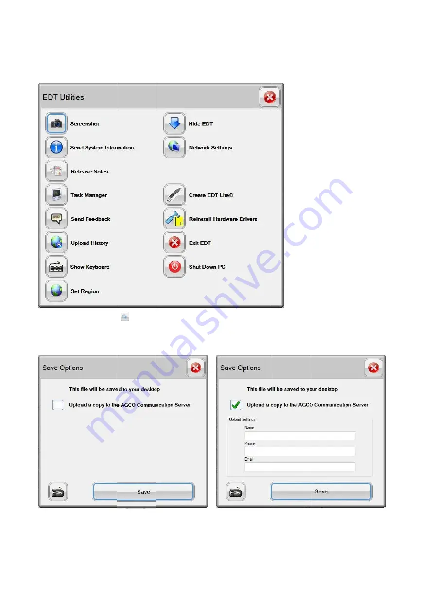
FIG.69
operations of 

Screenshot

FIG.70 & 71
saved to the desktop. If selecting to upload to the AGCO Communication Server, fill in the necess
to submit the image. Select 


Utilities


FIG.69


The Utilities

operations of 

Screenshot


FIG.70 & 71


saved to the desktop. If selecting to upload to the AGCO Communication Server, fill in the necess
to submit the image. Select 


Utilities


icon 

operations of the tool. 


In the box that appears, specify if the image will be uploaded to the AGCO Communication server or just 

saved to the desktop. If selecting to upload to the AGCO Communication Server, fill in the necess
to submit the image. Select 


icon 


(see EDT Utilities on page 22)

In the box that appears, specify if the image will be uploaded to the AGCO Communication server or just 

saved to the desktop. If selecting to upload to the AGCO Communication Server, fill in the necess
to submit the image. Select Save


EDT Utilities on page 22)

In the box that appears, specify if the image will be uploaded to the AGCO Communication server or just 

saved to the desktop. If selecting to upload to the AGCO Communication Server, fill in the necess


EDT Utilities on page 22)


will guide the user through some of the more common 


In the box that appears, specify if the image will be uploaded to the AGCO Communication server or just 

saved to the desktop. If selecting to upload to the AGCO Communication Server, fill in the necess


will guide the user through some of the more common 

In the box that appears, specify if the image will be uploaded to the AGCO Communication server or just 

saved to the desktop. If selecting to upload to the AGCO Communication Server, fill in the necess


will guide the user through some of the more common 

In the box that appears, specify if the image will be uploaded to the AGCO Communication server or just 

saved to the desktop. If selecting to upload to the AGCO Communication Server, fill in the necess


will guide the user through some of the more common 

In the box that appears, specify if the image will be uploaded to the AGCO Communication server or just 

saved to the desktop. If selecting to upload to the AGCO Communication Server, fill in the necessary details to be able 


39

will guide the user through some of the more common 


In the box that appears, specify if the image will be uploaded to the AGCO Communication server or just 

ary details to be able 


39


will guide the user through some of the more common 


In the box that appears, specify if the image will be uploaded to the AGCO Communication server or just 

ary details to be able 

Summary of Contents for EDT

Page 1: ...1 SERVICE TOOL OPERATOR MANUAL Electronic Diagnostic Tool EDT 22 01 2014...

Page 2: ...2 2...

Page 3: ...Wireless Network 15 Connecting to a LAN Network 16 USB Port 16 Care of the Diagnostic Terminal 17 Diagnostic Terminal Durability 17 Cleaning the Screen 17 Replacing Screen Protector 17 EDT Software 1...

Page 4: ...ration 59 Configuration 60 Diagnostic Test 61 Software Flash 62 Software Package Flash Multiple Files 62 Individual File Flash 62 Diagnostic Trouble Codes 63 Active Codes 63 Stored Fault Codes 65 Faul...

Page 5: ...ogram for EDT kits purchased with a diagnostic terminal not renewed the EDT application will work for a limited period of time after the renewal expiration date but eventually will become non function...

Page 6: ...which means the terminal will withstand moderate shock and vibration during use The screen is fluid resistant including oil with a replaceable protective cover It is advised to treat the EDT diagnosti...

Page 7: ...9 System Diagnostic Terminal Components FIG 4 and back terminal view Hard drive activity LED Battery LEDs 1 and 2 Speakers Fingerpr nt Reader Digital Microphone Array RAM modules 2 SODIMM slots Dockin...

Page 8: ...ction Buttons SAS Screen Rotation Lithium Ion Batteries Top terminal view Modular Expansion S System Ventilation Transmitter Power S Bluetooth Transmitter Power S System Power Switch DC In power in ha...

Page 9: ...e touch screen Smooth even pressure on the screen will result in prolonged screen life Do NOT use any objects other than the stylus that comes with the terminal or a finger tip Do not use pencils pens...

Page 10: ...ted on the vehicle cab window attached to the work platform allowing hands Make sure not to obstruct the view from the operator seat Make sure the window or other smooth surface is clean before attach...

Page 11: ...is self scratches and damage due to bumps Use the screen protector to extend the touch screen life The EDT convenience kit comes with four items Screen protector replacements pack Docking station with...

Page 12: ...is recommended for use during vehicle software reflashing procedures where loss of terminal power during the procedure could lead to vehicle controller damage thru of all functional ports on the diag...

Page 13: ...2 It is highly recommended the 90 degree USB cable be used for all USB connections to the terminal e 2x4 CAN USB protocol adapter ation to the electrical system for the machine EHICLE COMMUNICATION I...

Page 14: ...you plug in the module for slot cannot be accessed with the terminal inside the bump case Most devices extend out past the edge of the terminal which prevents the terminal from being used with the cas...

Page 15: ...be entered correctly in both text fields or connection to the network will not be possible Your network administrator should correctly you should now be connected wirelessly If you have trouble connec...

Page 16: ...of AC powered USB devices over USB powered devices be used for best results Low power devices USB memory devices SD Card readers can be us The diagnostic terminal is designed to connect to the intern...

Page 17: ...s intact for handling Align the screen protector with the terminal screen Press down the adhesive exposed side and ca protector in order to peel off the remaining paper strip Press along the edges of...

Page 18: ...d on the EDT diagnostic terminal and or any resident laptop This makes technical support o If additional software is installed the EDT software application as well as other software programs may stop...

Page 19: ...mation on the On Screen keyboard see On Screen Keyboard on page 27 Select the language by pressing on the Language icon 2 Fill in the complete Voucher Code your Dealer Code and Postal Code if applicab...

Page 20: ...the If the entry was not valid the above screen will the submission or If the validation is successful the above screen will be displayed If the entry was not valid the above screen will the submissi...

Page 21: ...cess the EDT brand selection page shows the message displayed If registration cannot be completed contact the appropriate Technical Support location as listed on the screen REGION SET UP After the reg...

Page 22: ...on that represents the country where the EDT is currently be The region will be displayed at the bottom of the EDT main screen on the bottom right The Region menu will appear Select the region Select...

Page 23: ...away from the dealership This connection can be completed with a wireless or LAN connection cable using the on board connection capabilities of the EDT diagnostic terminal Obtain and install a cellul...

Page 24: ...t will be available FIG 41 It is possible to check for an update at any time by double pressing on the XMS Agent icon in the desk top This dialog box will appear after the icon is selected Package siz...

Page 25: ...something wrong with the connection If this message is displayed select OK and connect the license still does not update select the Utilities icon After a software update a screen will be displayed w...

Page 26: ...ge is displayed select OK and connect the EDT to the internet The license wi license still does not update select the Utilities icon 6 for more information the system time and date are accurat If the...

Page 27: ...screen keyboard automatically appears if text input is required for a specific EDT application function ard input is required a keyboard icon 1 is supplied on the display When the keyboard icon is se...

Page 28: ...pdate Laptop Requirements Recommended PC Requirements for New Purchases Minimum PC Requirements Optimal Performance Limited Performance Hardware Industrial laptop computer or semi ruggedized touch scr...

Page 29: ...29 Installation Procedure FIG 49 Insert the EDT CD Select Run FIG 50 This screen will be displayed as the file is downloaded...

Page 30: ...30 FIG 51 Select Run FIG 52 Windows Installer is verifying the data to your computer FIG 53 This dialog will appear when the computer is initializing the installation...

Page 31: ...FIG 54 Shut down all windows programs before continue with EDT install Select Next 1 to continue FIG 55 This dialog ask you to select the folder where to install the EDT program Select Next 2 to conti...

Page 32: ...32 FIG 56 This dialog ask you to select the installation type of the EDT program Select Next 3 to continue FIG 57 Ready to install Select Next 4...

Page 33: ...DT program Do not cancel FIG 59 There will be some add on configuration settings FIG 60 After software installation is complete restart your computer Select OK Remember to connect the EDT to the inter...

Page 34: ...printer user s manual for configuration steps NON AGCO APPROVED SOFTWARE Non AGCO approved software can be loaded on the diagnostic terminal The system is not a locked unit It is STRONGLY RECOMMENDED...

Page 35: ...tion on page 37 Language Selection see Language Selection on page 38 shows status of the battery at all times USB Presence icon see Help on page 36 Utilities on page 39 OPERATION On the header of all...

Page 36: ...ct to scroll one page at a time Select to scroll one line at a time up and down to scroll to different parts of the user guide To change the language of the EDT User Guide select the appropriate langu...

Page 37: ...is loaded The available brands will be available on the Home Page Select a brand to select a vehicle for diagnosis The brands displayed on this screen will only be the brands associated with your Deal...

Page 38: ...nto the system where EDT is running the CAN mark 1 This means the CAN USB is present If the CAN will display with a red circle and slash 1 on the EDT screens USB is not connected a message box will ap...

Page 39: ...ough some of the more common In the box that appears specify if the image will be uploaded to the AGCO Communication server or just saved to the desktop If selecting to upload to the AGCO Communicatio...

Page 40: ...nect to the in An additional control icon will be added to the top right display in front of the EDT and can capture any aspect of the EDT functional unresponsive To capture an image go to the desired...

Page 41: ...ility will be available System Check process This is a stand alone process that will run in the background After selecting the Send System Information icon tility will be available System Check proces...

Page 42: ...code will be returned after the file has been Release notes are available at any time using the Release Notes The check takes several minutes to complete A copy will be placed on the desktop and if t...

Page 43: ...s to the EDT support group fill out your contact information and comments then select the SUBMIT icon to load the Windows to load the User Feedback form To send comments to the EDT support group fill...

Page 44: ...e A submission code will be returned after the file has been uploaded Select the Upload History icon will load the Upload History log The Upload History log details all content that has been uploaded...

Page 45: ...on on pages 21 and 22 for more information Hide EDT FIG 84 To minimize EDT down to the task bar and work directly with the operating system select the Hide EDT icon from the Utilities main screen FIG...

Page 46: ...Down PC icon to shut down the PC To setup and test the network connection select the t the current connection by selecting the Test Connections icon 1 access the internet through a proxy server Reins...

Page 47: ...roduced vehicles are based on the Automation Configuration AC numbers FIG 89 To select a model highlight the model using the up and down arrows at the right or use the touch screen Then press the Sele...

Page 48: ...lectrical schematics and component locations Once the vehicle has been loaded in the EDT the machine specific information can be viewed any time during the diagnostic section by selecting the Informat...

Page 49: ...N when connecting to a vehicle The vehicle must be OFF during connection of the EDT to A group of navigation icons appears after the Diagnostics Connection page until after a vehicle has been selected...

Page 50: ...CAN Network Status 3 Network Scan shows all the available ECUs on the network channel and the connection status of each Green LED ECU is available Red LED ECU is absent Yellow LED ECU is optional Whi...

Page 51: ...be displayed on this page if the information is available CAN Network Status FIG 97 CAN Network Status shows a graph plotted between the CAN Bus Load in Percentage and Time The Error Count will also...

Page 52: ...ction to perform a diagnostic review of a specific vehicle system NOTE Consult the specific machine s service manual for information on how to use the EDT diagnostic functions for the machine NOTE The...

Page 53: ...phical surface of the desired function to be diagnosed A list of available graphical surfaces for the selected function will be available Graphical Diagnostics arrow icons 2 to select the desired surf...

Page 54: ...gnal Description signal Value and ECU name in a grid view Select the single arrow icons 1 to scroll through each row Select the double arrow icons 2 to scroll through each page If you want a specific...

Page 55: ...vailable View Signal Trace Plot Multiple Signals Signals are recorded as an Excel file with a csv extension icon to play back recorded signals allows the option to select or deselect the signals to be...

Page 56: ...to preview selected signals in one graph Select a an individual recorded signal Previewing of this signal is also available in graph analog or digital view Diagnostics Reporting Signal Play Back Windo...

Page 57: ...tly from the storage location Diagnostics Reporting Signal Trace Window Each recorded signal log with a csv extension can be viewed in a grid layout To the list shown or change the selection of the fi...

Page 58: ...the desired drive if the files will be uploaded to the AGCO Communication Server 4 From the Signal Trace Window either all files or a single file can be uploaded to a selected drive fixed drive 1 to...

Page 59: ...n Versu Direct Hitech 5PS Range Gear Calibration Versu Direct Hitech 5PS Hydrostatic Unit Direct only Speed Sensor Calibration F clutch Calibration R clutch Calibration C1 clutch Calibration Versu Hit...

Page 60: ...the tractor model Save TC1 indexes to EDT Load TC1 indexes to EDT Update TC1 indexes with latest factory values Adjust TC1 indexes Adjust Tractor Terminal Indexes Reset Tractor Terminal User Settings...

Page 61: ...s Follow the instructions given by EDT Available diagnostic tests for Valtra Suolahti vehicles vary depending of the tractor model Hydrostatic Unit Test Direct only Visco Fan Test Cylinder Cut Out Tes...

Page 62: ...he USB connector Software Package Flash Multiple Files Select a Software Package 1 to be flashed Select the Start icon 3 to start batch flashing The Flash Scripts in each flash file will guide the fla...

Page 63: ...on the vehicle ne 1 to scroll through the fault codes 2 to scroll through the pages When the desired fault code is highlighted select the 4 to retrieve the first and last occurrence information 5 to...

Page 64: ...ation schematics overview etc Navigate under diagnostic fault tree by using the arrow icons or scroll Home icon 1 to show the fa 2 to print the entire fault tree 3 at the top to go backward or forward...

Page 65: ...nformation to an Excel Select stored codes to view all stored fault codes for the controller on the vehicle network Select the icon 1 at the bottom center of the screen and select STORED CODES Navigat...

Page 66: ...the top to display desired ECM fault codes Navigate through the fault codes using the scroll arrows or vertical and horizontal From the fault code screen view the Fault Tree Index by selecting the Al...

Page 67: ...2 to upload CAN logs fo to upload individual CAN logs for ed to a fixed driv to run the Script to start recording of the CAN traffic icon 1 to record the CAN log This icon toggles between 2 to upload...

Page 68: ...ools file from the list on the left hand side icon 4 to show the recorded CAN trace log 5 to toggle between full screen view and partial screen view 6 to change the name of the file 7 to delete a file...

Page 69: ...flashing on the vehicle network controllers After installation on a computer EDT Lite will function for 180 days after which the user will be notified to re create the application IMPORTANT EDT Lite...

Page 70: ...re the EDT Lite Creator is to be placed target drive If multiple installations of EDT Lite are required install the EDT Lite creator onto a USB memory device Select the icon 1 next to Select an output...

Page 71: ...71 FIG 128 Select the content to be created for EDT Lite by selecting the box next to the required region 3 Select brand 4 to be included for EDT Lite Select Create Installation 5 to start the process...

Page 72: ...s the installation process 7 Select the Close icon 8 when the process is complete FIG 130 If the target drive is not large enough a dialog box will appear To resolve do one of the following Reduce the...

Page 73: ...he new EDT Lite installation to the network burn to a CD copy to a flash drive or test by creating EDT Lite on the target drive NOTE All of the files in this folder are required for the installation p...

Page 74: ...to be installed Navigate to the target drive and locate EDT Lite Setup exe Double click on the file Follow the instructions on the screen to install NOTE It is recommended to copy the EDT Lite Install...

Page 75: ...desktop FIG 138 The heading at the top of the screen identifies the Lite application 2 Since EDT Lite is created from the full EDT application there is no need to authorize the subscription license A...

Page 76: ...ons are shown but according to a prompt 3 the software maintenance is not functional All other function icons work exactly like the full EDT application NOTE For software maintenance on a vehicle the...

Page 77: ...N USB Presence 38 CAN USB Presence Icon 35 Cigarette Lighter Adapter 12 Cleaning the Screen 17 Configuration 49 60 Connecting to a LAN Network 16 Connecting to a Wireless Network 15 Contents 3 Conveni...

Page 78: ...0 8 G Getting Started 35 Graphical Diagnostics 53 Graphic Screen 53 H Hard Drive LED 7 Headphone Jack 8 Help 35 36 Hide EDT 45 Home Page 37 I Index 77 Individual File Flash 62 Installation Procedure 2...

Page 79: ...Set Region 45 Shut Down PC 46 Signal Play Back 56 Signal Trace 57 Snapshot Data 63 Software Flash 49 62 Software Package Flash 62 Software Updating 23 Speaker 7 Stored Fault Codes 65 Stylus Pen 8 Subs...

Page 80: ...80 User Feedback 43 Utilities 35 39 V Vehicle Communication Interface 13 Vehicle Selection 47 View Uploads 44 W WiFi Switch 8 15 Work Platform 10...

Reviews: