


41
DESN 513532
DESN 512415
DESN 513530
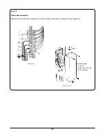
Fig. 15.14
Fig. 15.15
Fig. 15.16
K. TO REMOVE ELECTRODE
(LEFT HAND BURNER) (
Fig. 15.14
)
1.
Isolate from electrical supply.
2.
Proceed as ‘
TO REMOVE HOTPLATE
’.
3.
Proceed as ‘
TO REMOVE SPARK GENERATOR
’.
4.
Disconnect the left hand burner pipe (13mm) and the
inner burner pipe (13mm) using the special spanner.
5.
Remove the burner and burner fixing plate, by
unscrewing the (4) screws holding the burner mounting
plate in place.
6.
Turn burner over and remove electrode fixing clip.
Withdraw electrode through top of burner checking on
route of lead.
7.
Re-assemble in reverse order, re-routing lead along the
same path.
L.
TO REMOVE THERMOCOUPLE
(LEFT HAND FRONT BURNER) (
Fig. 15.15
)
1.
Isolate from electric supply.
2.
Proceed as ‘
TO REMOVE THE HOTPLATE
’.
3.
Undo the nut fixing the thermocouple in place.
4.
Push the thermocouple down and pull out from under
the burner.
5.
Disconnect the other end of the thermocouple cable
from the gas valve. This is a push on jack connector.
6.
Re-assemble in reverse order.
M. TO REMOVE THERMOCOUPLE
(LEFT HAND REAR, RIGHT HAND REAR, RIGHT
HAND FRONT BURNERS)
1.
Isolate from electric supply.
2.
Proceed as ‘
TO REMOVE THE HOTPLATE
’.
3.
Undo the nut fixing the thermocouple in place.
4.
Push the thermocouple down and slide to the side to
remove from the burner.
5.
Disconnect the other end of the thermocouple cable
from the gas valve, this is a push on electrical terminal.
6.
Re-assemble in reverse order.
N. TO REMOVE GRILL LINERS -
Fig. 15.6
1.
Remove left hand and right hand runners (4 screws per
runner).
2.
Remove runners and liners.


