


29
12. Installation sequence and procedure
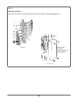
Gas connection
n
n
CAUTION: ENSURE THAT THE APPLIANCE IS
ISOLATED FROM ELECTRIC SUPPLY
The appliance can be installed with an approved flexible
connection. Supply piping
SHOULD NOT
be less than 3/8 I/D.
Connection is made to the R1/2 (1/2”BSP) female threaded fitting
located just below the hotplate level on the rear left-hand
side of the appliance.
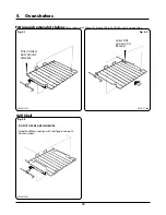
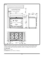
The gas bayonet connector provided, must be fitted to the
wall in the shaded area dimensioned in (
Fig. 12.1
) and (
Fig.
12.2)
. Take into account that it must be possible to pull the
appliance forward sufficiently for servicing. Ensure flexible
hose is not trapped between appliance back panel and rear
wall. Ensure hose is routed away from the vent slots in the
back panel. The flexible hose must be in accordance with the
relevant standards.
n
n
IMPORTANT: The gas supply connection at the wall
must not project out from the wall by more than
45mm, so that it does not foul with the back of the
appliance Fig. 12.2.
FLEXIBLE HOSE
The flexible hose must be suitable with the type of gas being
used. LPG hoses carry a red stripe, band or label. If in doubt
ask your supplier.
For an appliance other than an upright appliance, which may
be connected with a hose assembly. The supply connection
point must be accessible with the appliance installed.
NOTE
: Use soapy water solution on new gas connections to
ensure there are no gas leaks.
Check for gas tightness after connecting the appliance.
Pressure testing
The pressure test point is situated at the rear right hand side
of the hotplate.
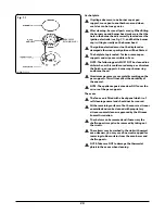
Place the wok burner head, burner cap and ring into
position on the hotplate. Light the burner by pushing in
the appropriate control knob, and turning it anti-clockwise
IGNITION
position, until gas ignites, then continue to turn to
the
FULL ON
position.
For natural gas appliance, the pressure should be 20mbar (8
inches water gauge).
For NL only the pressure should be 25mbar.
Turn off the tap, disconnect the pressure gauge and refit test
point blanking screw.


