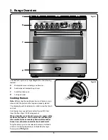
background image

11

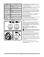
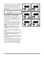
Rotate the Adjusting knob to set the time required 

(Fig.2-26)

.

You can either turn the knob back to the vertical manual 

setting [

] to keep an eye on the time of day, or leave it in the 

[

] minute minder position as the time ticks down.

To stop the beeper when it sounds, turn the Adjusting knob 

counter-clockwise.

• 

The ‘cook period’, which is the length of time you 

want the oven to cook for.

• 

The ‘stop time’, which is the time of day you want the 

oven to stop cooking.

To Stop the Oven at a Specific Time of Day

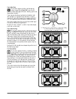
Turn the Timer knob to the [

] position 

(Fig.2-27)

.

Use the Adjusting knob to set the ‘stop time’. You can set 

the oven to turn on at any time over the following 24-hour 

period. AUTO shows in the display 

(Fig.2-28)

.

Turn the Timer knob to the bottom ‘AUTO’ setting to return to 

the clock display.
Once the ‘stop time’ is reached, the beeper sounds. Turn the 

Timer knob to the vertical [

] to return to manual cooking.

To Start and Then Stop the Oven Using the 
Timer

You cannot set a start time directly – this is set 

automatically by a combination of the 

‘cook time’

 and  

‘stop time’.
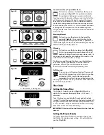
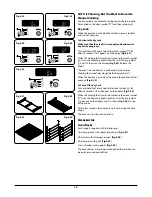
Turn the Timer knob to the [

] position 

(Fig.2-29)

.

Turn the Adjusting knob to set the 

cooking time’ you need 

(Fig.2-30)

.

Turn the Timer knob to the [

] position. The display will show 

the current time of day plus the 

cook time’ you just set. Use 

the Adjusting knob to set the ‘stop time’ required  

(Fig.2-31)

.

The 

stop time’ is displayed, followed by ‘AUTO’. Set the oven 

to the cooking temperature you need. Turn the Timer knob to 

the ‘Auto’ setting.
When your cooking is finished, the beeper sounds. Turn the 

Timer knob to the vertical [

] to return to manual cooking.

If you are out, do not worry about the beeper going off – it 

stops on its own after a while. When you return, turn the 

Timer knob to the vertical [

] to return to manual cooking.

Fig.2-28

Fig.2-29

ArtNo.300-0006 2BC

minute minder setting 2

ArtNo.301-0007 2BC

Stopping the oven 1

ArtNo.301-0008 2BC

Stopping the oven 2

ArtNo.301-0009 2BC

Setting the cooking timer

ArtNo.301-0010 2BC

Setting the cooking time

ArtNo.301-0008 2BC

Stopping the oven 2

Fig.2-27

Fig.2-26

Fig.2-30

Fig.2-31

Summary of Contents for Professional 90 Dual Fuel

Page 1: ...90 Dual Fuel User Guide Installation Service Instructions U110246 01 Professional ...

Page 2: ...tinual improvement we reserve the right to change specifications without prior notice 6 Cleaning Your Range 19 Essential Information 19 Daily Care 19 Cleaning for Spills 19 Cooktop Burners 19 Griddle Optional Extra 20 Control Panel and Oven Doors 20 Self clean Oven 20 Cleaning Table 22 7 Installation 24 Regulations 24 Installation Safety Instructions 24 Converting to Propane Gas 24 Location of the...

Page 3: ...rt Many plastics will burn and most are damaged by heat Keep plastic items away from parts of the range that may become warm or hot Do not leave plastic items on the cooktop as they may burn melt or soften if left too close to a vent or a lighted burner Storage should not be installed directly above a range If anything is stored above the range it should be limited to infrequently used items which...

Page 4: ...fornia to cause cancer birth defects or other reproductive harm Users of this appliance are hereby warned that the burning of gas can result in low level exposure to some of the listed substances including benzene formaldehyde and soot due primarily to the incomplete combustion of natural gas or liquid petroleum LP fuels Properly adjusted burners will minimize incomplete combustion Exposure to the...

Page 5: ... divider and all other utensils Placement of Oven Racks n n Always place oven racks in desired location while oven is cool If rack must be moved while oven is hot do not let potholder contact hot heating element in oven n n CAUTION DO NOT store items of interest to children in cabinets above a range or on the backguard of a range children climbing on the range to reach items could be seriously inj...

Page 6: ...s of the pan Carefully watch for spills or overheating of foods when frying at high or medium high temperatures Never try to move a pan of hot fat especially a deep fry pan Wait until the fat is cool When an oven is on do not use the top of the flue the holes along the back of the range for warming plates dishes drying dish towels or softening butter When using an electrical appliance near the coo...

Page 7: ...rner that knob controls Each burner has a special Flame Safety Device FSD that stops the flow of gas if the flame goes out When a hotplate control knob is pressed in sparks will be made at every burner this is normal Do not attempt to disassemble or clean around any burner while another burner is on otherwise an electric shock could result To light a burner push in the selected burner control knob...

Page 8: ...hat may tilt easily and pans with a very small base diameter e g milk pans single egg poachers Fig 2 7 The minimum pan diameter recommended is 4 12cm for the outer burners and 6 3 8 16cm for the center burner Igniting Cooktop Burners without Electricity If there is a power failure the cooktop burners can be lit with a match 1 Hold a burning match from the burner head keeping your hand as far horiz...

Page 9: ... allow plenty of time for it to cool before you pick it up The Multi function Oven IMPORTANT Before using the oven for the first time to dispel manufacturing odors turn the oven to 395 F 200 C in fan assisted mode and run for one hour To clear the smell make sure the room is well ventilated to the outside air by opening windows or turning on your ventilation hood n n DO NOT drop or rest objects on...

Page 10: ...5 Multi function Oven Modes Fig 2 16 Thaw and Serve This function operates the fan s to circulate cold air only Fig 2 17 No heat is applied This enables small items such as desserts cream cakes and pieces of meat fish and poultry to be defrosted Thawing in this way speeds up the process and protects the food from contamination Pieces of meat fish and poultry should be placed on a rack over a tray ...

Page 11: ...broiler The oven door should be kept closed while cooking is in progress so saving energy You will also find that the food needs to be watched and turned less than for normal broiling Rack levels 5 and 6 should be used depending on the size of the food being cooked Fan Assisted Oven This function operates the fans circulating air heated by the elements at the top and the base of the oven Fig 2 20 ...

Page 12: ...warming The Browning and Warming functions are useful additions to your oven giving you flexibility to finish off items to perfection With use you will soon realize how these functions can combine to extend your cooking skills Self Cleaning The oven has a self cleaning function The oven will run at a high temperature cycle to burn any cooking residue to ash that is easily cleaned away with a damp ...

Page 13: ...the Timer You cannot set a start time directly this is set automatically by a combination of the cook time and stop time Turn the Timer knob to the position Fig 2 29 Turn the Adjusting knob to set the cooking time you need Fig 2 30 Turn the Timer knob to the position The display will show the current time of day plus the cook time you just set Use the Adjusting knob to set the stop time required F...

Page 14: ...ob to the clock symbol for about 8 seconds OF will appear on the display Fig 2 35 While still holding the Timer knob turned to the clock symbol turn the Adjusting knob clockwise until the key symbol goes out on the display and On shows Fig 2 36 Let go of the knobs After a few seconds the display reverts to showing the time of day The oven can now be used normally Accessories Oven Racks Each range ...

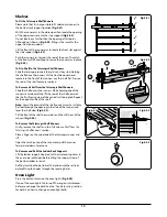
Page 15: ...ers securely carefully lift the rear of the shelf upwards the shelf will spring clear of the central restraining tab Repeat for the opposite side of the shelf Note To aid the removal of the shelf you can insert a suitable flat tool through the opening in the side of the runners and lever the shelf clear Fig 2 43 Tilt the front of the shelf downwards and then lift clear of the runners Fig 2 44 To R...

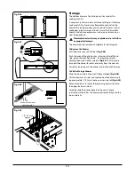
Page 16: ... ends of the plastic clips down on the left hand side up on the right hand side to release the catches holding the drawer to the side rails Fig 2 47 At the same time pull the drawer forwards and away from the side rails For safety reasons push the drawer rails back out of the way To Fit the Storage Drawer Slide the inner side rails out until fully extended Fig 2 48 Lift the drawer at its sides and...

Page 17: ...oultry must be thoroughly defrosted before being placed in the oven Check that meat and poultry are fully cooked before serving 3 Cooking Tips General Oven Tips The wire racks should always be pushed firmly to the back of the oven Baking trays with food cooking on them should be placed level with the front edge of the oven s wire racks Other containers should be placed centrally Keep all trays and...

Page 18: ... 30 minutes interchange after 15 minutes 25 30 minutes interchange after 15 minutes 10 15 minutes interchange after 15 minutes 40 60 minutes 20 30 minutes Temperature F C 300 150 375 190 300 150 375 190 300 150 375 190 300 150 375 190 300 150 375 190 300 150 375 190 300 150 350 180 350 180 275 140 275 140 300 150 300 150 325 165 375 190 350 180 350 180 275 140 425 220 325 165 350 180 350 180 350 1...

Page 19: ...sed by heat rising from the oven and heating them up Do not leave the oven door open 5 Troubleshooting If there is an installation problem and I don t get my original installer to come back to fix it who pays You do Service organizations will charge for their service if they are correcting work carried out by your original installer It is in your interest to track down your original installer Powe...

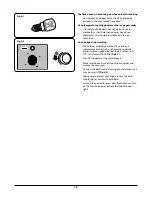
Page 20: ... can buy a replacement bulb which is not covered under the warranty from a good electrical shop Ask for a 15W 125 130V lamp FOR OVENS Fig 5 1 Turn off the power at the circuit breaker Make sure the oven is cool Open the oven door and remove the oven racks Unscrew the bulb cover by turning counter clockwise It may be very stiff Fig 5 2 Taking care to protect your fingers in case the bulb should sha...

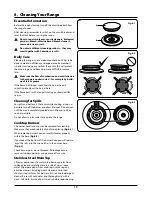
Page 21: ...n as possible turn off the burner and allow it to cool Do not clean until the area is completely cooled down Wipe up spills as soon as possible Do not allow surplus water to seep into the range Cooktop Burners The burner heads and caps can be removed for cleaning Make sure they are absolutely dry before replacing Fig 6 1 When replacing burner head ensure this locates properly within the base Fig 6...

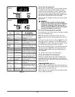
Page 22: ...en the door slightly and using the handle carefully lift the door outer upwards Refit in reverse Self clean Oven n n WARNING Remove all cookware racks and the rack supports from the oven before using the self clean function If the racks and supports are left in the oven they will discolor and become rough n n DO NOT clean the door gasket the door gasket is essential for a good seal Care should be ...

Page 23: ...splay will now show a P Fig 6 8 The Timer knob and Adjusting knob are shown in Fig 6 9 Turn the Timer knob to the position Fig 6 10 to set the default cleaning time 3 hours To adjust the cleaning cycle duration rotate the adjusting knob see Table 6 1 Note that the maximum time for the self cleaning operation is 4 hours The cooling fan will switch to high speed and as soon as a certain temperature ...

Page 24: ...ly To Cancel the Automatic Self cleaning Cycle To return to manual operation the Cleaning period must be cancelled Turn the Timer knob to the position and rotate the Adjustment knob counter clockwise until the timer display reads 0 00 Cleaning Table Table 6 2 Cleaners listed are available from supermarkets or electrical retailers as stated For enamelled surfaces use a cleaner that is approved for ...

Page 25: ...from a neighbor s phone Follow the gas supplier s instructions If you cannot reach your gas supplier call the fire department Installation and service must be performed by a qualified installer service agency or the gas supplier WARNING The anti tip device supplied with this range must be installed when the appliance is installed This will reduce risk of tipping of the appliance from abnormal usag...

Page 26: ...ecting gas and electrical supply to range Have your range installed by a qualified installer Your range must be electrically grounded in accordance with local codes or in the absence of local codes in accordance with the National Electrical Code ANSI NFPA 70 latest edition Before installing your range on linoleum or any other synthetic floor covering make sure the floor covering can withstand 180 ...

Page 27: ...Teflon that resists action of natural and LP gases Flexible metal appliance connector I D A 5 foot length is recommended for ease of installation but other lengths are acceptable Never use an old connector when installing a new range Flare union adapter for connection to gas supply line or NPT x I D Flare union adapter for connection to pressure regulator on range NPT x I D To protect any floor co...

Page 28: ...of your range The location of the electrical outlet and pipe opening see Gas Pipe and Electric Outlet Locations may be adjusted to meet specific requirements A gap of at least 3 7 5 cm should be left between each side of the range ABOVE the cooktop level and any adjacent vertical surface The cooktop surround should be level with or above any adjacent work surface For non combustible surfaces such ...

Page 29: ...ached or removed to prevent it being disturbed when moving the range around Removing the Oven Door To remove the door open the door fully Swivel the locking U clips forward to the locking position Fig 7 4 Grip the sides of the door lift upwards and then slide the door forwards Fig 7 5 and remove Removing the Storage Drawer Pull the drawer right out Push the ends of the plastic clips down on the le...

Page 30: ...g 7 9 Leveling It is recommended that you use a spirit level on a rack in the oven to check for level Place the range in its intended position taking care not to twist it within the gap between the kitchen units as damage may occur to the range or the units The front feet and rear rollers can be adjusted to level the range To adjust the height of the rear of the cooker use a 13mm spanner or socket...

Page 31: ...ge These can be installed where the side of the range is exposed preferably during the installation of the appliance Procedure 1 Loosen the 2 screws in the rear edge of the range side panel 2 Using the cut outs locate the side extension onto the protruding screw heads Fig 7 13 3 Push the side extension up to so that the tab in the bottom of the flue extension fits into the slot at the top Fig 7 14...

Page 32: ...a licensed electrician install an approved outlet Because range terminals are not accessible after range is in position flexible service conduit or cord must be used Provide Proper Electrical Supply This range must be supplied with 240 V 60 Hz and connected to an individual properly grounded branch circuit protected by a circuit breaker or time delay fuse If the electrical service provided does no...

Page 33: ...t Insert the conduit through the reducer plates on the mounting bracket Fig 7 19 Allow enough slack to easily attach the wires to the terminal block Note DO NOT install the conduit without a squeeze connector Attach the wires to the ground post and terminal block Fig 7 20 Note Make sure the wires are completely inserted into the terminals and secure connections are made Secure the squeeze connecto...

Page 34: ...a 11 8 diameter opening for conduit connection Find the reducer plates Fig 7 23 in the conversion kit and fix them to the mounting bracket Install a squeeze connector not supplied with the range to your conduit Insert the conduit through the reducer plates on the mounting bracket Allow enough slack to easily attach the wires to the terminal block Fig 7 24 Note DO NOT install the conduit without a ...

Page 35: ...essure of 10 of water column 2 49 kPa is required n n Make sure you are supplying your range with the correct type of gas If the range is to be used on LP gas a qualified LP installer MUST convert it We recommend that the range be converted before installation This must be done before the range can be used on LP gas For proper operation the pressure of natural gas supplied to the regulator must be...

Page 36: ...g to avoid damage When installing the range from the front remove the 90 elbow for easier installation C Install a male or flare union adapter to the NPT internal thread of the manual shut off valve taking care to backup the shut off valve to keep it from turning D Connect a flexible metal appliance connector to the adapter on the range Position the range to permit connection at the shut off valve...

Page 37: ...er or socket wrench to turn the adjusting nuts at the front bottom corners of the cooker To set the front feet turn the bases to raise or lower Final Fitting Installing the Toe Kick Remove the 3 screws for the toe kick mounts along the front bottom edge of the range Fig 7 30 Fasten the toe kick using these screws alternative color screws can be found in the loose parts pack Fitting the Grates Make...

Page 38: ...Check each burner in turn There is a flame safety device that stops the flow of gas to the burner if the flame goes out There is also a spark ignition system that works when the knob is pressed in For each burner push in and turn a knob to the lighting position The igniter should spark and light the gas Keep holding the knob pressed in to let the gas through to the burner for few seconds If when y...

Page 39: ...vant regulations and also the local electricity supply company requirements Read the instructions before converting this appliance Failure to convert the appliance correctly could invalidate any warranty or liability claims and lead to prosecution This instruction must be used in conjunction with the rest of the appliance instruction in particular for information on Standards range positioning con...

Page 40: ...ront lip of the hob Fit the 6 fixing screws and control knobs See Table 8 2 for screw sizes Gas Regulator To access the gas regulator remove the storage drawer Pull the drawer right out Push the ends of the plastic clips down of the left hand side up on the right hand side to release the catches holding the drawer to the side rails Fig 8 4 At the same time pull the drawer forwards and away from th...

Page 41: ... appliance to the gas supply Check the appliance is gas sound The gas pressure can be measured at the pressure test point on the appliance side of the pressure regulator Fig 8 11 For proper operation the pressure of LP supplied to the regulator must be between 10 and 13 of water column 2 49 3 24 kPa When checking for proper operation of the regulator the inlet pressure must be at least 1 0 25 kPa ...

Page 42: ...extended Fig 8 13 Lift the drawer at its sides and locate one of the drawer rails approximately 15mm onto an inner side rail Fig 8 14 Rotate the drawer to locate the remaining drawer rail onto the opposite inner side rail Carefully slide the drawer back into the cavity Some resistance will be felt as the drawer rails locate fully onto the inner side rails n n Check the appliance is gas sound n n C...

Page 43: ...en front switch C1 Right hand oven base element C2 Right hand oven top outer element C3 Right hand oven top inner element C4 Right hand oven fan element C5 Right hand oven fan D Cooling fan 2 speed F1 Left hand oven base element F2 Left hand oven top outer element F3 Left hand oven top inner element F4 Left hand oven fan element F5 Left hand oven fan Code Color bl Blue br Brown bk Black or Orange ...

Page 44: ...ob Bypass Screw Natural gas 4 WC Propane gas 10 WC Input Orifice Input Orifice Large burner 49 17 500btu hr 205 17 500btu hr 118 Medium burner 38 12 500btu hr 150 12 500btu hr 99 Small burner 31 6 000btu hr 112 6 000btu hr 68 The valves in this range are fitted with adjustable bypass screws The range is supplied with the bypass screws set for Natural gas For LPG conversion the bypass screws must b...

Page 45: ...43 ...

Page 46: ...44 ...

Page 47: ...use and alteration or the removal or defacing of the serial plate cancels all obligations of this warranty Service during this warranty must be performed by a factory Authorized Service Person 2 Warranty applies to product only in the country in which it was purchased 3 AGA is not liable for any claims or damages resulting from any failure of the range or from service delays beyond their reasonabl...

Page 48: ...www aga ranges com AGA Marvel 1260 E VanDeinse St Greenville MI 48838 Business 616 754 5601 Fax 616 754 9690 Toll Free Telephone 800 223 3900 ...

Reviews: