background image

53

SPECIFICATIONS

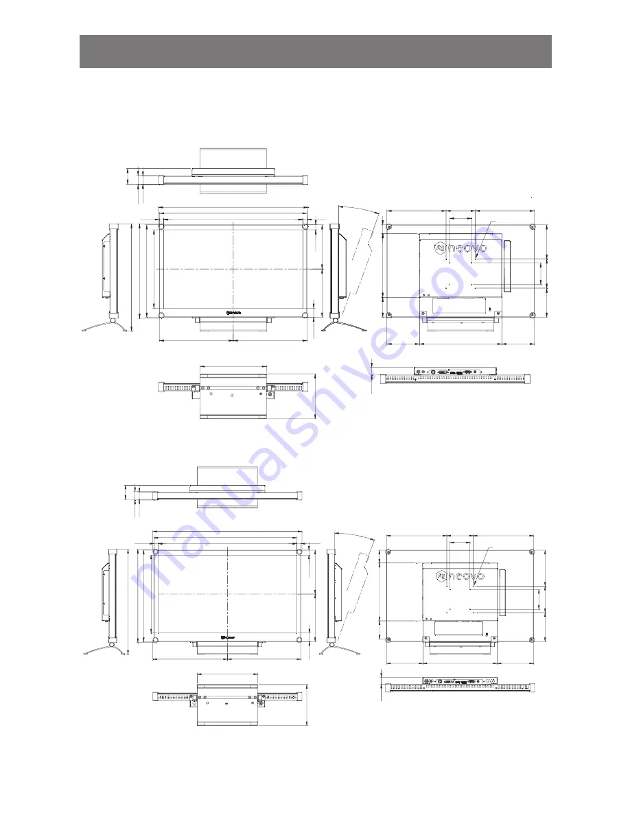
7.2 Display Dimensions

7.2.1    MX-22 Dimensions

477.8(opening dimension)

505.6

513.2(outline  dimension)

26

9.

2(

op

en

in

di

me

ns

io

n)

31

6.

7

32

4.

3(

ou

tlin

di

me

ns

io

n)

252.8

252.8

15

1.

35

16

5.

35

75

100

10

0

11

7.

45

99

.2

5

202.8

202.8

(M4xL10) x8

75

32

.6

27

.4

227.4

15

5

36

8.

5

30

.4

21

7.

8

68

.5

111.6

282.4

111.6

53

.5

13.9

30

.7

5

13.9

16

.7

5

26

.1

0°~15°

7.2.2    MX-24 Dimensions

522.3(opening dimension)

538.55

562.4(outline  dimension)

29

4.2(

op

en

in

di

me

ns

io

n)

34

5

35

2.

6(

ou

tlin

di

m

ens

io

n)

281.2

277.4

165.

5

17

9.5

75

100

10

0

13

5.75

10

9.25

227.4

227.4

(M4xL10) x8

75

32

.6

27

.4

227.4

15

5

39

6.

8

48.7

21

7.

8

68

.5

137.4

280

137.4

53

.6

4

16.25

32

.4

16.25

18

.4

26

.1

0°~15°

AG Neovo

Company Address: 5F-1, No. 3-1, Park Street, Nangang District, Taipei, 11503, Taiwan.

Copyright © 2017 AG Neovo. All rights reserved.                                                                                                      MX-22/MX-24_UM_V010

Summary of Contents for MX-22

Page 1: ...MX 22 MX 24 LED Backlit Display User Manual ...

Page 2: ... 2 Rear View 18 Chapter 2 Making Connections 2 1 Connecting the Power 19 2 2 Connecting Input Source Signals 20 2 2 1 Connecting a Computer 20 Using VGA Cables 20 Using DVI Cables 20 Using DisplayPort Cables 21 Using Audio Cables 21 2 2 2 Connecting a Video Device 22 Using HDMI Cables 22 Chapter 3 Using the LCD Display 3 1 Turning on the Power 23 3 2 Selecting the Input Source Signal 23 3 3 Adjust...

Page 3: ... 39 5 6 ANTI BURN IN 41 5 7 OSD SETTING 42 5 8 AUDIO SETTING 43 5 9 SYSTEM 44 5 10 ECO SMART 46 5 11 INPUT SELECT 47 Chapter 6 Appendix 6 1 Warning Messages 48 6 2 Troubleshooting 49 6 3 Transporting the LCD Display 51 Chapter 7 Specifications 7 1 Display Specifications 52 7 2 Display Dimensions 53 7 2 1 MX 22 Dimensions 53 7 2 2 MX 24 Dimensions 53 ...

Page 4: ...cur in a particular installation If this equipment does cause harmful interference to radio or television reception which can be determined by turning the equipment off and on the user is encouraged to try to correct the interference by one or more of the following measures Reorient or relocate the receiving antenna Increase the separation between the equipment and receiver Connect the equipment i...

Page 5: ...h country in the European Union should have its collection centers for electrical and electronic equipment recycling For information about your recycling drop off area please contact your local related electrical and electronic equipment waste management authority or the retailer where you bought the product Standard Test item Standard EN60601 1 2 2007 RAD CON EN55011 EMI Harmonic EN61000 3 2 Flic...

Page 6: ...o verify normal operation in the configuration in which it will be used Anyone who connects additional equipment to the signal input part or signal output parts configuring a medical system responsible that the system complies with the requirements of IEC EN60601 1 2 Guidance and manufacturer s declaration electromagnetic emissions The MX 22 and MX 24 is intended for use in the electromagnetic env...

Page 7: ...ld be that of a typical commercial or hospital environment Voltage fluctuations flicker emissions IEC EN61000 3 3 5 UT 95 dip in UT for 0 5 cycle 40 UT 60 dip in UT for 5 cycles 70 UT 30 dip in UT for 25 cycles 5 UT 95 dip in UT for 5 sec 5 UT 95 dip in UT for 0 5 cycle 40 UT 60 dip in UT for 5 cycles 70 UT 30 dip in UT for 25 cycles 5 UT 95 dip in UT for 5 sec Mains power quality should be that o...

Page 8: ...rference by maintaining a minimum distance between portable and mobile RF communications equipment transmitters and the MX 22 and MX 24 as recommended below according to the maximum output power of the communications equipment Rated maximum output power of transmitter W Separation distance according to frequency of transmitter m 150kHz to 80MHz d 1 2 P 80MHz to 800MHz d 1 2 P 800MHz to 2 5GHz d 2 ...

Page 9: ... STAND BY IEC 60417 5031 Direct Current IEC 60417 5032 Alternating Current IEC 60417 5021 Equipotentiality Notice Read this User Manual carefully before using the LCD display and keep it for future reference The product specifications and other information provided in this User Manual are for reference only All information is subject to change without notice Updated content can be downloaded from ...

Page 10: ...display on a stable area Do not place the LCD display where it may subject to vibration or shock Place the LCD display in a well ventilated area Do not place the LCD display outdoors Do not place the LCD display in a dusty or humid environment Do not spill liquid or insert sharp objects into the LCD display through the ventilation holes Doing so may cause accidental fire electric shock or damage t...

Page 11: ...leaning Do not use liquid or spray detergents for cleaning Use a damp cloth Keeping to clean your monitor by monthly The LCD display comes with NeoVTM Optical Glass Use a soft cloth to clean the glass surface and the housing The display can be cleaned using a cloth moistened with 95 ethyl alcohol Do not rub or tap the surface of the glass with sharp or abrasive items such as a pen or screwdriver T...

Page 12: ...disappear after a few days or as soon as the weather stabilizes There are millions of micro transistors inside the LCD display It is normal for a few transistors to be damaged and to produce spots This is acceptable and is not considered a failure The intended use of the MX 22 MX 24 is to serve as a LCD monitor for integration with the hospital system It is designed for general purpose for adults ...

Page 13: ...inst the ingress of water IPX0 WARNING Do not modify this equipment without authorization of the manufacturer Installation and OSD adjusting should only be carried by manufacturer trained and authorized personnel WARNING To avoid risk of electric shock this equipment must only be connected to a supply mains with protective earth CAUTION This adapter Manufacturer model is a forming part of the medi...

Page 14: ...Actual items may vary upon shipment VGA cable Power adapter LCD Display Audio cable Note Must use only the supplied power adapter Adaptor Technology Model no ATM065 P120 Rating 12V 5A Adaptor Technology Model no ATM065T P120 Rating 12V 5A EDAC Technologies Corporation Model no EM10681G Rating 12V 4 16A Chapter 1 Product Description Warranty card MX 22 MX 24 www agneovo com MX 22 MX 24_Quick Guide_...

Page 15: ...jury and damage to the display in case of earthquakes or other disasters Use only the 75 x 75 mm and 100 x 100 mm wall mount kit recommended by AG Neovo Secure the LCD display on a solid wall strong enough to bear its weight Note To protect the glass panel place a towel or soft cloth before laying the LCD display down Warning Ceiling mount or mount on any other horizontal surface overhead are not ...

Page 16: ...AP the PIP main and sub picture When PIP is off press to select picture mode STANDARD DICOM During OSD menu selection press to move down a menu or submenu 3 LEFT Hot Key Volume Down Press to display the volume screen Then press again to decrease the volume During OSD menu selection press to adjust the settings 7 MENU Press to display the OSD menu Press again to hide the OSD menu 8 SOURCE Press to ...

Page 17: ...ng a DisplayPort cable for digital input signal 2 DVI connector Use to connect a PC using a DVI cable for digital input signal 5 VGA connector Use to connect a PC using a VGA cable for analogue input signal 3 HDMI connector Use to connect an input device using an HDMI cable for digital input signal 6 Audio port Use to connect an audio cable for the PC s audio input 3 4 5 6 2 ...

Page 18: ...Connect the power cord plug to a power outlet or a power supply DC IN Caution Make sure that the LCD display is not connected to the power outlet before making any connections Connecting cables while the power is ON may cause electric shock or personal injury Caution When unplugging the power cord hold the power cord by the plug head Never pull by the cord Chapter 2 Making Connections ...

Page 19: ...ng VGA Cables Connect one end of a VGA cable to the VGA connector of the LCD display and the other end to the VGA connector of the computer VGA Using DVI Cables Connect one end of a DVI cable to the DVI connector of the LCD display and the other end to the DVI connector of the computer DVI ...

Page 20: ...o the DisplayPort connector of the LCD display and the other end to the DisplayPort connector of the computer DisplayPort Using Audio Cables Connect one end of an audio cable to the audio port at the rear of the LCD display and the other end to the audio out port of the computer AUDIO IN ...

Page 21: ... MAKING CONNECTIONS 2 2 2 Connecting a Video Device Using HDMI Cables Connect one end of an HDMI cable to the HDMI connector of the LCD display and the other end to the HDMI connector of your device HDMI ...

Page 22: ...efer to page 44 After selecting an input source signal the input source signal message appears on the screen briefly For example HDMI is selected the following message is displayed H D M I I N P U T If the selected input source signal is not connected to the LCD display or is turned off the no signal message is displayed on the screen N O S I G N A L If the resolution or the graphics card of the c...

Page 23: ...SD press and hold the keypad buttons listed below for at least 5 seconds or until the O S D L O C K O U T message appears When the OSD is locked all keypad buttons are inactivated Type of OSD Lock Lock Operation Unlock Operation Lock all buttons Touch and hold the u p and q buttons for 5 seconds Touch and hold the u p and q buttons for 5 seconds or until the OSD menu appears Lock all buttons excep...

Page 24: ...s follows PIP On The sub source signal is displayed within the main source signal PBP Picture by Picture The main source and the sub source signals are displayed side by side with equal display size PIP Off PIP function is disabled only the main source signal is displayed Note The main source and sub source signals can be set in PIP Setting see page 39 Some input source signal combinations do not ...

Page 25: ...ncluding horizontal position vertical position clock and phase Touch the button to perform auto adjustment The message auto adjusting is displayed on the screen A U T O A D J U S T I N G During auto adjustment the screen will slightly shake for a few seconds When the message disappears auto adjustment is completed Note PIP Swap can only be executed if PIP is enabled see page 40 Note Auto Adjustmen...

Page 26: ...E C T B R I G H T N E S S 5 0 B L A C K L E V E L 5 0 B A C K L I G H T 5 0 C O N T R A S T 5 0 Touch 2 Select the menu 1 9 2 0 x 1 0 8 0 6 0 H z B R I G H T N E S S C O L O U R T E M P I M A G E S E T T I N G A S P E C T R A T I O P I P S E T T I N G A N T I B U R N I N O S D S E T T I N G A U D I O S E T T I N G S Y S T E M E C O S M A R T I N P U T S E L E C T L A N G U A G E I N F O R M A T I ...

Page 27: ...L E V E L 5 0 B A C K L I G H T 5 0 C O N T R A S T 5 0 A D J U S T The highlighted item with an orange arrow indicates the active submenu Touch the p or q button 4 Adjust the settings Touch the t or u button 5 Exit the submenu Touch or to return to the previous menu 6 Close the OSD window Touch or again When settings are modified all changes are saved when the user does the following Proceeds to ...

Page 28: ...H POSITION V POSITION PHASE CLOCK See page 35 1 9 2 0 x 1 0 8 0 6 0 H z B R I G H T N E S S C O L O U R T E M P I M A G E S E T T I N G A S P E C T R A T I O P I P S E T T I N G A N T I B U R N I N O S D S E T T I N G A U D I O S E T T I N G S Y S T E M E C O S M A R T I N P U T S E L E C T L A N G U A G E I N F O R M A T I O N E X I T E N T E R S E L E C T B R I G H T N E S S 5 0 B L A C K L E V ...

Page 29: ...P See page 39 6 ANTI BURN IN ENABLE INTERVAL HOURS MODE See page 41 7 OSD SETTING TRANSPARENCY OSD H POSITION OSD V POSITION OSD TIMER See page 42 8 AUDIO SETTING VOLUME AUDIO SOURCE See page 43 9 SYSTEM POWER SAVING SOURCE DETECT MODE DDC CI DCR BLUE SCREEN SIGNAL INFO HDMI CEC LOGO RECALL See page 44 10 ECO SMART ENABLE MODE LEVEL See page 46 11 INPUT SELECT VGA DVI HDMI DP See page 47 ...

Page 30: ...enu Submenu Remarks 12 LANGUAGE Select the OSD language EN FR DE ES IT PY RO PL CS NL 简中 繁中 13 INFORMATION Displays settings information such as Input Resolution Horizontal Frequency Vertical Frequency Timing Mode and Firmware Version ...

Page 31: ...R A S T 5 0 A D J U S T 1 Touch to call out the OSD window 2 Select BRIGHTNESS menu then touch the u button 3 Touch the p or q button to select an option Item Function Operation Range BRIGHTNESS Adjusts the luminance of the screen image Touch the t or u button to adjust the value 0 to 100 CONTRAST Adjusts the difference between the black level and the white level BACKLIGHT Adjusts the luminance of...

Page 32: ...33 ADJUSTING THE LCD DISPLAY Original Setting High Setting Low Setting BRIGHTNESS CONTRAST BLACK LEVEL ...

Page 33: ...Provides several colour settings Touch the t or u button to select the setting NEUTRAL WARM COOL USER Colour setting can be set to NEUTRAL commonly used for normal lighting conditions WARM Applies a reddish tint for warmer colours COOL Applies a bluish tint for cooler colours USER This allows users to set the colour temperature by adjusting the R G B settings according to one s preference 1 Select...

Page 34: ... E M O D E D I C O M S T A N D A R D E X I T S E L E C T A D J U S T L O W M I D H I G H O F F H P O S I T I O N 5 0 V P O S I T I O N 5 0 1 Touch to call out the OSD window 2 Select IMAGE SETTING menu then touch the u button 3 Touch the p or q button to select an option Item Function Operation Range SHARPNESS Adjusts the clarity and focus of the screen image Touch the t or u button to adjust the ...

Page 35: ...l Please select Monitor OSD colour range Limit Signal source from Video Video signal at a limited range Grayscale 16 235 state Monitor OSD colour range Limit Please select Monitor OSD colour range Full NOISE REDUCTION Adjusts the noise reduction to help remove noise from images This helps produce clearer and crisper images Touch the t or u button to select the setting OFF LOW MID HIGH Noise Reduct...

Page 36: ...adjust the value 0 to 100 V POSITION Vertical Position Moves the screen image up or down PHASE Adjusts the phase timing to synchronise with the video signal Note This menu option is only available if the input source is VGA CLOCK Adjusts the frequency timing to synchronise with the video signal Note This menu option is only available if the input source is VGA ...

Page 37: ...uch to call out the OSD window 2 Select ASPECT RATIO menu then touch the u button 3 Touch the p or q button to select an option Item Function Operation Range ASPECT RATIO Adjusts the aspect ratio of the screen image Touch the t or u button to select the setting FULL REAL ZOOM H ZOOM Horizontal Zoom Adjusts the horizontal zoom Note This menu option is only available if the ASPECT RATIO setting is t...

Page 38: ...1 1 2 3 S U B P I C P O S L U R U L D R D R D E X I T S E L E C T A D J U S T 1 Touch to call out the OSD window 2 Select PIP SETTING menu then touch the u button 3 Touch the p or q button to select an option Item Function Operation Range PIP Allows you to select the PIP setting or disable PIP Touch the t or u button to select the value OFF PIP PBP PIP can be set to OFF Disables PIP PIP The sub so...

Page 39: ...he setting L U R U L D R D The position of the sub source image can be set to L U Sets the image on the upper left corner of the screen R U Sets the image on the upper right corner of the screen L D Sets the image on the lower left corner of the screen R D Sets the image on the lower right corner of the screen SWAP Swaps the main source and sub source signals Touch the u button to execute the func...

Page 40: ...S T 1 Touch to call out the OSD window 2 Select ANTI BURN IN menu then touch the u button 3 Touch the p or q button to select an option Item Function Operation Range ENABLE Enables or disables Anti Burn In function Touch the t or u button to select the setting ON OFF INTERVAL HOURS Sets the interval time hour between activating the Anti Burn In function Touch the t or u button to adjust the value ...

Page 41: ... 1 5 E X I T S E L E C T A D J U S T 1 Touch to call out the OSD window 2 Select OSD SETTING menu then touch the u button 3 Touch the p or q button to select an option Item Function Operation Range TRANSPARENCY Adjusts the transparency level of the OSD screen Touch the t or u button to adjust the value 0 to 100 OSD H POSITION Horizontal Position Moves the OSD window to the left or right of the scr...

Page 42: ...D J U S T 5 0 1 Touch to call out the OSD window 2 Select AUDIO SETTING menu then touch the u button 3 Touch the p or q button to select an option Item Function Operation Range VOLUME Adjusts the volume level of the built in speaker Note If volume is adjusted but AUDIO is set to OFF no sound comes out from the speaker Touch the t or u button to adjust the value 0 to 100 AUDIO Turns the audio speak...

Page 43: ...o call out the OSD window 2 Select SYSTEM menu then touch the u button 3 Touch the p or q button to select an option Item Function Operation Range POWER SAVING Enables or disables power saving mode When the LCD display turns into power saving mode the screen turns black and the LED indicator lights AMBER Note The amount of time for the display to enter power saving varies depending on the SOURCE D...

Page 44: ...mic Contrast Ratio Activates DCR This feature provides automatic adjustment of picture brightness and contrast at high speed and dynamic contrast range such as when watching movies DCR is suitable for indoor viewing BLUE SCREEN Enables or disables the blue screen feature If the setting is set to ON it displays a blue screen when no signal is available SIGNAL INFO Enables or disables the signal inf...

Page 45: ... O F F L E V E L A U T O U S E R 8 0 E X I T S E L E C T A D J U S T 1 Touch to call out the OSD window 2 Select ECO SMART menu then touch the u button 3 Touch the p or q button to select an option Item Function Operation Value ENABLE Enables or disables the Eco Smart feature Touch the t or u button to select the setting ON OFF MODE Sets the auto brightness mode Touch the t or u button to select t...

Page 46: ...E C T L A N G U A G E I N F O R M A T I O N V G A D V I H D M I D P E X I T E N T E R S E L E C T 1 Touch to call out the OSD window 2 Select INPUT SELECT menu then touch the u button 3 Touch the p or q button to select an option Item Function Operation Value VGA Sets VGA as the input source signal Touch the u button to switch to the selected input source DVI Sets DVI as the input source signal HD...

Page 47: ... graphics card N O S I G N A L The LCD display cannot detect the input source signal Check if the input source is turned ON Check if the signal cable is properly connected Check if any pin inside the cable connector is twisted or broken O S D L O C K O U T The OSD has been locked by the user Unlock the OSD Refer to page 24 A N T I B U R N I N O N The Anti Burn In function has been enabled by the u...

Page 48: ...rs inside the LCD display It is normal for a few transistors to be damaged and to produce spots This is acceptable and is not considered a failure No audio output Check if the volume is set to 0 see page 24 or 43 Check if the AUDIO SETTING AUDIO setting is set to OFF see page 43 For VGA or DVI input check the audio setting of the computer For HDMI or DP input select the correct audio input source ...

Page 49: ...ther conditions This is a normal occurrence The mist will disappear after a few days or as soon as the weather stabilizes Faint shadows from a static image appear on the screen Turn off the LCD display for extended periods of time Use a screen saver or a black and white image and run it for extended periods of time ...

Page 50: ...ce the display in its original packaging carton 1 Put all the accessories in the box if necessary Place the two foam cushions on each side of the LCD display for protection 2 Place the LCD display down in the box 3 Place the accessories box on the designated area if necessary 4 Close and tape the box ...

Page 51: ...D HDMI HDMI DisplayPort DisplayPort Audio Audio In Stereo audio jack for PC 3 5mm Speaker Out 2W x 2 Power In Power Supply External Power Requirements DC 12V 2 5A Consumption 19W On 18W On 0 5W Stand by 0 5W Stand by 0 5W Off 0 5W Off Operating Conditions Temperature 0 C 40 C 32 F 104 F Humidity 10 90 Altitude 0 3000m Transport Storage Conditions Temperature 20 C 60 C 4 F 140 F Humidity 5 95 Altit...

Page 52: ...82 4 111 6 53 5 13 9 30 75 13 9 16 75 26 1 0 15 7 2 2 MX 24 Dimensions 522 3 opening dimension 538 55 562 4 outline dimension 294 2 opening dimension 345 352 6 outline dimension 281 2 277 4 165 5 179 5 75 100 100 135 75 109 25 227 4 227 4 M4xL10 x8 75 32 6 27 4 227 4 155 396 8 48 7 217 8 68 5 137 4 280 137 4 53 64 16 25 32 4 16 25 18 4 26 1 0 15 AG Neovo Company Address 5F 1 No 3 1 Park Street Nan...

Reviews: