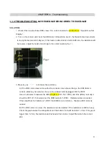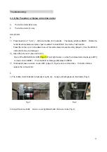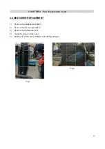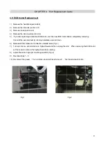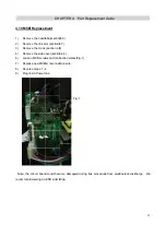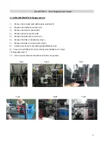
4.11 Flyw
1)
Remo
2)
Remo
3)
Remo
4)
Remo
5) Remov
6) Reinst
7) Check
Tensio
Wrenc
8) The rec
4) Torque
Fig-4
wheel and
ve the handl
ve the link a
ve the crank
ve the side c
ve the flywhe
tall new Flyw
k the tension
on on the driv
ch.
commended
bolt to 300kg
Fig-1
CHA
Drive belt
lebar (section
rm (section 4
k (section 4.8
cover (sectio
eel and drive
wheel & drive
with equipm
ve belt is 185
belt allowan
gF-cm (Fig-6
APTER 4:
t replacem
n4.6)
4.7)
8)
n.4.4)
e belt by loos
e belt (Fig-1)
ment. The ten
5Hz - 195Hz
ce does not
6)
Part Rep
ment
sening the te
nsion specific
. If specific
/- 1
Fig-2
Fig-5
placement
ension bolts o
cation is 185
cations canno
1mm (Fig-4).
Guide
on either side
HZ-195HZ, T
ot be confirm
Adjust with
e of the flywh
The recomm
med, adjust th
h a wrench.
F
Fig-
34
heel bracket
ended
he belt with a
Fig-3
-6
4
a
Summary of Contents for Pro 7.2AI
Page 2: ...Pro oduct B Browse e 2 2...
Page 5: ...1 1 Serial l Number CH Location HAPTER 1 Serial Number Loca ation 5 5...
Page 8: ...2 2 Engin neering mo ode instruc CHAPTER ction R 2 Console Instru uction 8 8...
Page 9: ...CHAPTER R 2 Console Instru uction 9 9...
Page 10: ...3 1 ELEC 7 2AI SCH CTRICAL D HEMATIC DIAGRAM MCB EC CHAPTER CB R 3 Troubleshooting 10 0...
Page 11: ...Console c connection n layout CHAPTER R 3 Troubleshooting 11...


