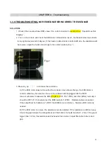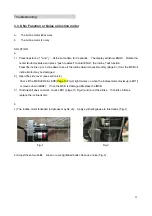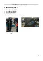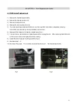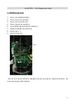
4.10 MCB
1)
Remo
2)
Remo
3)
Remo
4)
Remo
6)
Loose
7)
Replac
8)
Rever
9)
Plug in
Note: the
recommend
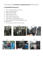
B Replacem
ve the handl
ve the link a
ve the crank
ve the side c
en MCB screw
ce new MCB
rse steps 1 -
n AC Power
circuit board
d wearing an
CHA
ment
lebar(section
rm (section 4
k (section 4.8
cover(section
ws and conn
B & reconnec
4
line
d could beco
ESD wrist s
APTER 4:
n4.6)
4.7)
8)
n.4.4)
nection wires
ction wire.
F
ome damage
strap.
Part Rep
s (Fig-1)
ig-1
ed during th
placement
his procedure
Guide
e from elect
trostatic disc
33
charge. We
3
e
Summary of Contents for Pro 7.2AI
Page 2: ...Pro oduct B Browse e 2 2...
Page 5: ...1 1 Serial l Number CH Location HAPTER 1 Serial Number Loca ation 5 5...
Page 8: ...2 2 Engin neering mo ode instruc CHAPTER ction R 2 Console Instru uction 8 8...
Page 9: ...CHAPTER R 2 Console Instru uction 9 9...
Page 10: ...3 1 ELEC 7 2AI SCH CTRICAL D HEMATIC DIAGRAM MCB EC CHAPTER CB R 3 Troubleshooting 10 0...
Page 11: ...Console c connection n layout CHAPTER R 3 Troubleshooting 11...

