aFe Power SCORCHER BLUE 77-83043, Instruction Manual
The aFe Power SCORCHER BLUE 77-83043 is a high-performance tuning module designed to enhance horsepower and torque in your vehicle. For step-by-step installation and usage guidance, be sure to download the free Instruction Manual from manualshive.com. Maximize your driving experience with this powerful product at your fingertips.
Share
Download


Reviews:
No comments
Related manuals for SCORCHER BLUE 77-83043

ATEX
Brand: Vega Pages: 68

AR-FN6
Brand: Olivetti Pages: 39

50131
Brand: A-Tach Mounts Pages: 2

WINE CAPTAIN U-2115WCOL-00
Brand: U-Line Pages: 5

RUNA
Brand: 2E GAMING Pages: 26

BICI OK 2
Brand: Fabbri Pages: 4

HAZARDOUS ROOM Series
Brand: aci Pages: 3

DUCT Series
Brand: aci Pages: 4

DNF10
Brand: CAME Pages: 2

SR-A260
Brand: AA Products Pages: 4

Wireless Rain Sensor
Brand: R&D Pages: 8

VIEWLINE 52 MM - MOUNTING 11-09
Brand: VDO Pages: 4
DTT9001
Brand: Jiuzhou Pages: 30

Prime Chime Plus
Brand: NICOR Pages: 4
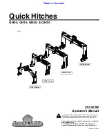
QH05 Series
Brand: Land Pride Pages: 38

WEY VV5
Brand: Great Wall Pages: 18

IDS 410
Brand: Industrial Data Systems Pages: 63

WP9378
Brand: WIX Pages: 2


