background image


48


                                                                              Aeroworks 30cc Freestyle Extra 260 Assembly Manual 


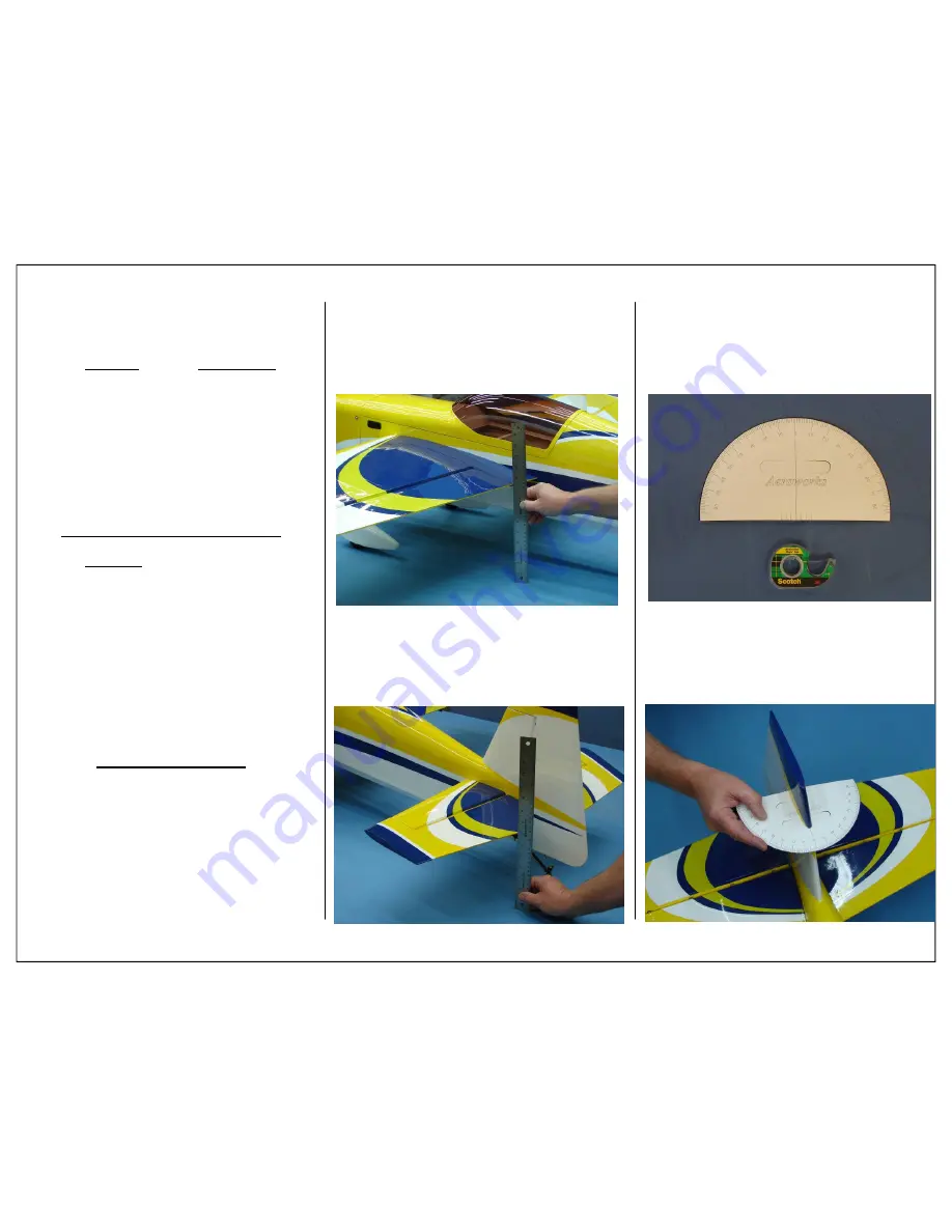
1.  Use the widest part of the aileron as shown to 

measure the aileron throw in inches. 

2.  Use the widest part of the elevator as shown to 

measure the elevator throw in inches. 


 Low 

Rate Medium 

Rate 


Aileron


1 1/2” or 15˚ up 

2 1/4” or 25˚ up 


1 1/2” or 15˚ down  2 1/4” or 25˚ down 


Rudder

 15˚ left 

30˚left 

 15˚ right 

30˚right 


Elevator

  7/8” or 12˚ up 

1 1/2 ” or 20˚ up 


7/8” or 12˚ down 

1 1/2” or 20˚ down 


For 3D flying use the following throws: 

 
 High 

Rate 


Aileron


3 1/2” or 40˚ up 


3 1/2” or 40˚ down   


Rudder

 45˚ left 


 45˚ right 
 

Full rudder deflection is typically  


recommended for all out 3D 


Elevator

  3 3/4” or 50˚ up 


3 3/4” or 50˚ down   


Recommend Expediential:  


25% expediential on low rates   


45% expediential on medium rates  


60% expediential on high rates  


Use the given rates as a starting point.  Then 
adjust rates to suit your own flying style.


CONTROL THROW  

DEFLECTION TABLE  

3.  Gather the Aeroworks Rudder Throw Meter 

(

Supplied

)  and clear tape. 


4.  Slide the throw meter under the rudder boost tab. 

Summary of Contents for 30cc Extra 260 Freestyle

Page 1: ......

Page 2: ...ARF QB L has been individually hand built cov ered and painted by trained and experienced craftsmen with over 25 years of manufactur ing experience CAD design laser cutting technology and jig built pa...

Page 3: ...Number 11 12 13 14 15 16 17 18 19 20 21 22 23 24 25 26 Item Description Carbon Fiber Wing Tube Carbon Fiber Stab Tube Wing Stab Mounting Hardware 15oz Fuel Tank w hardware Carbon Landing Gear w hardw...

Page 4: ...954SH Servos are recommended for unlim ited flying These servos will provide the best per formance possible Note Servos available through Aeroworks 5 Hitec 7954SH Servos for flight surfaces 1 Hitec 63...

Page 5: ...Extensions 22 AWG extensions are recommended throughout the 30cc Freestyle Extra 260 QB L The following sizes will be used 2 3 Extensions For Receiver to Ailerons 2 6 Extensions For Ailerons 2 24 Ext...

Page 6: ...u will be re warded with a long lasting beautifully covered model TIGHTENING AND RESHRINKING THE COVERING 2 Using your covering iron with a soft sock gently apply pressure and rub in the covering If a...

Page 7: ...thin CA on the front canopy mounting tabs as shown DO NOT install canopy on the fuse until glue has fully cured Failure to do so may cause canopy to be permanently glued to the fuse 1 The ailerons ha...

Page 8: ...Brass spacer goes between servo arm and ball link and is not installed between the right and left control horns 4 Place aileron control horns into the pre cut slot with the base plate installed Use a...

Page 9: ...check this alignment while the epoxy cures it is very im portant that the control horn is correctly aligned with the hinge line 12 Fasten the pull string from the servo hole to the male plug of the se...

Page 10: ...is will allow for easier removal at a later date These screws can be purchased from Micro Fasteners part number SCM2508 15 Install servo with servo mounting screws Re peat servo installation process f...

Page 11: ...Fastener Part number STW0209 recommended 1 1 1 4 Servo Arm 1 24 Servo Extension 1 Aeroworks Safety Clip Required Tools and Adhesives 80 Grit Sandpaper 5 Minute Epoxy Hobby Knife Ball Point Pen STAB AN...

Page 12: ...e of removed covering shown below 14 Apply 5 minute epoxy into the control horn mounting slots and the base plate mounting loca tion as shown 9 Use 80 grit sandpaper to scuff the carbon control horn a...

Page 13: ...while making the initial linkage adjustments 18 A pushrod adjustment wrench has been in cluded this will allow the pushrod length to be extended or shortened with out removing the servo arm Adjust the...

Page 14: ...opropyl Alcohol Paper Towels Builders Tip Wet paper towels with isopropyl alcohol before starting rudder installation This will make cleaning any excess epoxy easier once the rudder is installed 3 Mix...

Page 15: ...ounting hardware 1 3 Double Output servo arm Required Tools and Adhesives 1 16 Ball Driver Small Phillips screw Driver Wire Cutters Pliers 1oz Bottle Thick CA Glue Masking Tape RUDDER SERVO PULL PULL...

Page 16: ...damage the wood underneath the covering 8 Use 80 grit sandpaper to scuff the carbon control horn where it will pass through the rudder 9 Use 80 grit sandpaper to lightly scuff the back of the control...

Page 17: ...14 Install the remaining 4 40 ball link as shown 15 Before the epoxy has fully cured ensure that full rudder travel can be achieved If the control horns come in contact with the fuse at full throw the...

Page 18: ...to the nose of the airplane 21 Feed one rudder cable through the pre installed cable exit tube in the rear of the fuse toward the front of the fuse Repeat for other side 16 Finished rudder control ho...

Page 19: ...e through brass swage tube 26 Thread cable through the threaded coupler hole and back through the brass swage tube as shown 27 Loop the cable back through the brass swage tube and pull tight 22 Loop o...

Page 20: ...ll 32 Tape the rudder balance tab to the top leading edge of the vertical fin in the neutral position as shown This ensures the rudder is straight when the cables are attached 33 Plug the rudder servo...

Page 21: ...crews 1 Steering Tiller 2 Tiller Mounting Screws 2 Steering Springs Required Tools and Adhesives Phillips Screw Driver Pliers Wire Cutters 1oz Bottle Gap Filling CA Glue Notice Please note optional ca...

Page 22: ...of rudder 3 Apply a drop of thick CA to the tiller arm mounting screws before inserting in the pre drilled holes 5 Align the tail wheel with pre drilled mounting holes on the bottom of the fuse 6 Plac...

Page 23: ...re that the springs allow for full rudder deflection and that they do not bind 8 Attach the steering spring to the rudder tiller Center the spring between both tail wheel and steering tillers 9 Wrap s...

Page 24: ...l the axle into the gear strut with lock nut Lightly tighten axle lock nut at this time MAIN LANDING GEAR AND WHEEL PANT INSTALLATION 1 Gather the following items shown below for the main landing gear...

Page 25: ...inner wheel collar Use blue Loctite on the wheel collar set screw before final tighten ing 8 Install 3 wheel and outer wheel collar Use blue Loctite on the wheel collar set screw before final tighten...

Page 26: ...shown Use a square to align the propeller output shaft with the pre marked thrust lines on the template 4 Mark the location of the standoffs on the tem plate as shown Ensure that the engine does not m...

Page 27: ...fender washers to mount engine to firewall 4 Use blue Loctite to secure the engine mounting bolts in place This will insure that the mounting bolts stay in place over time 5 Tighten the bolts evenly t...

Page 28: ...iver 1 5 64 Ball Driver 1 Electric Drill 1 1 16 Drill Bit 1 7 64 Drill Bit 1 Rotary Cutting Tool with Cutting Disk 1 Wire Cutter 1 Soldering Iron 1 Silver Solder Sta Brite Recommended 1 80 Grit Sandpa...

Page 29: ...ring final installation 8 Assemble brass threaded coupler to 4 40 ball link Assemble ball link and brass spacer to the servo arm as shown below 9 With servo arm still 90 degrees to servo and throttle...

Page 30: ...ions Choke Installation 1 Gather provided choke installation items shown below 1 4 40 Metal Rod Threaded at One End 1 4 40 Ball Link Assembly with Hardware 1 4 40 Threaded Insert 1 Large Nylon Tie 2 S...

Page 31: ...NSTALLATION 2 Position the ignition module on the side of the engine mounting box and mark the location of the nylon tie holes as shown 3 Use a 1 4 bit to drill the ignition module mounting holes 4 Mo...

Page 32: ...Fuel Line 2 Small Nylon Ties Required Parts Not Included 1 Aeroworks Fuel Line Installation Kit Required Tools and Adhesives Pencil Felt Tip Pen Phillips Screw Driver Wire Cutter Soldering Iron Silver...

Page 33: ...the rubber stopper assembly into the tank with the vent tube at the top of the tank 9 Secure the rubber stopper with set screw Take care not to strip threads by over tightening set screw 6 Install air...

Page 34: ...ote It is recommended you always use a fuel filter on your gas can filters should not be installed inside the airplane Inline fuel filter can clog and cause your engine to quit T Fill Line Carb Vent L...

Page 35: ...e fuel dot higher than the clunk line of the fuel tank 10 Use a hobby knife to remove covering followed by the underlying balsa as shown below The use of a new blade is recommended for a clean easy cu...

Page 36: ...e to cut a hole in the bottom of the fuse forward of the landing gear plate to al low the fuel vent exit dot to pass through 16 Route the vent line through the hole made in the previous step and attac...

Page 37: ...e bottom cowl mounting blocks 5 Mark the side of the template that will come in contact with the cowling This will help when transferring the cut out locations onto the cowl COWL INSTALLATION 1 Gather...

Page 38: ...f clearance be tween the cowl and the motor Make any adjust ment to the cylinder head cut out at this time 6 Trace around the head of the engine being care ful to keep the template in the same locatio...

Page 39: ...is time 15 Check the fit of the template at this time It may be necessary to make small adjustments to the cutout to get it to fit properly 16 Align template with mounting bolt holes in cowl Use a fel...

Page 40: ...nd enlarge the stinger cutout for a proper fit 22 The front air inlets should be centered both verti cally and horizontally on the engine head This will allow cool air to pass through the cowl and int...

Page 41: ...shown below RADIO INSTALLATION 1 Gather the radio installation items as shown be low Required Parts 2 8x80x300mm Foam Pad 2 356x12 5mm Velcro Straps Required Parts Not Included 1 Receiver 6 8 Channel...

Page 42: ...to adhere firmly to the plywood radio floor 7 Finished regulator installation shown below Ensure that regulator is securely held to radio tray a one wrap strap can be placed around the regulator and...

Page 43: ...and into the wing root blind nuts Tighten snugly but do not over tighten and crack the fuse or wing root wood 7 Gather 4 4 40 stab mounting bolts and 4 6 small rubber backed washers these will be use...

Page 44: ...ly thin CA glue to the front hold down dowels This is a High vibration area and can loosen the front dowels Always check the front dowels are secure before each flying session 10 The canopy is secured...

Page 45: ...nner SFG mounting tab will pass through the wing and will secure to the bottom inner SFG 3 Place the top inner SFG into the precut slot in the wing as shown below 5 Secure the inner SFG s with a 4 40...

Page 46: ...own below 6 Factory decal placement shown below 1 Gather the items listed below for the installation of the supplied decal package Required Parts 1 Custom Decal Package Required Tools and Adhesives St...

Page 47: ...ies installed and READY TO FLY Try to balance the model by moving the batteries and receiver before adding any ballast 5 Attach loop to cable attachment as shown below 6 Slide wing back against fuse i...

Page 48: ...8 or 12 down 1 1 2 or 20 down For 3D flying use the following throws High Rate Aileron 3 1 2 or 40 up 3 1 2 or 40 down Rudder 45 left 45 right Full rudder deflection is typically recommended for all...

Page 49: ...p up the tail of the aircraft until the fuselage is parallel to the table top 8 Use the widest part of the aileron to measure the aileron throw in degrees 9 Use the widest part of the elevator to meas...

Page 50: ...Extra 260 settle in for a perfect 3 point landing It is always a good idea to check your air plane before each flying session Listed below are a couple of key areas that should be checked before each...

Page 51: ...associated with flying the model aircraft are allowed at or in front of the line In the case of air shows demonstrations straight line must be established An area away from the line must be maintained...

Page 52: ...4 4mm i d wheel collars with set screws 4 4 40x10mm button head bolts for wheel pants mounting 4 3mm flat washer for mounting wheel pants 4 3mm split ring lock washer for mounting wheel pants 2 2 75m...

Page 53: ...ting template DLE 30 OS GT33 DLE 35RA and universal 2 8x80x300mm sponge for the receiver and battery 3 356x12 5mm one wrap strap 3 large nylon ties 8 small nylon ties 1 card stock 8 x11 for making the...

Page 54: ...it perfectly on the 30cc Freestyle Extra 260 The carbon leaf spring adds tremendous strength compared to the stock aluminum tail wheel at a reduced weight Aeroworks Safety Clips Made from flexible pla...

Page 55: ......

Reviews: