


22. HYDRAULIC
CIRCUIT
The NRL consists ofTWO CIRCUITS both
fitted with:
−
Evaporators 1 x circuit
−
Water filter 1 per circuit (supplied)
supplied with log and victaulic gaskets
−
Desuperheaters
(2 per circuit in parallel mode)
without filter
−
Water inlet probe SIW
−
Water outlet probe SUW
NB:
The water outlet probe (WOP) with its
trap is free, near the electrical box,
remember to insert it in the collector
of the outlet hydraulic parallel, using a
sleeve of ½ inch.
22.1.
EXTERNAL HYDRAULIC CIRCUIT
RECOMMENDED
The selection and installation of components
outside the NRL should be carried out by
the installer, who should work according
to the technical code of practice and in
compliance with the legislation in force in
the country of destination (MD 329/2004).
Before connecting the pipes make sure that
they do not contain stones, sand, rust, slag
or any foreign bodies that may damage the
system. It is necessary to make a by-pass to
the unit to be able to carry out the cleaning
of the pipes without having to disconnect
the machine. The connection pipes must be
properly supported so as not to burden the
unit with their weight.
On the water circuit, it is advisable to install
the following instruments, if not foreseen in
the version you have:
1. Two pressure gauges of suitable size
(input and output section).
2. Two antivibrating couplings (input and
output section).
3. Two shut-off valves (normal input section,
output section calibrating valve).
4. Two thermometers (input and output
section).
5. Expansion
tanks
6. Pump
7. Accumulation
8. Flow
switch
9. Safety
valve
10. Charging unit
11. Chiller drain tap in the tube output
evaporator (for standard version)
NB:
In case of version with pumping unit,
without standby pump,
it is recommended to install
undirectional valves to the delivery of
each module.
So water reflow is avoided
in the circuit of the pump/s
from the other circuit.
For NRL 2250 model with pumping unit, it
is recommended the installation, to the
delivery of the module 1250, of a capacity
balance valve, to balance the capacities
between the two evaporators (module
1000 and 1250).
It is necessary, that the water flow rate to
the chiller unit complies with the values
reported in the performance tables.
The systems loaded with anti-freeze or
specific regulations, need the water
backflow system.
Special supply/recovery water, is carried
out with appropriate treatment systems.
22.2. SYSTEM
LOAD
−
Before starting the load, check that the
system drain tap is closed.
−
Open all the drain valves of the system
and of the related terminals.
−
Open the shut-off devices of the system.
−
Start the filling by slowly opening the
water system load cock placed outside
the machine.
−
When water begins to flow from the
terminal vent valves, close them and
continue loading up to read on the
gauge the value of 1.5 bar.
The system is loaded at a pressure between
1 and 2 bar.
It is advisable to repeat this operation
once the machine has worked for some
hours and to periodically check the system
pressure, restoring if it drops below 1 bar.
Check the hydraulic seal of the joints.
22.3. EMPTYING THE SYSTEM
−
Before starting to drain the system, turn
"off" the unit
−
Check that the water system load/
restore tap is closed
−
Open the drain tap outside the machine
and all the vent valves of the system
and the corresponding terminals.
−
In case of prolonged shut-down of the
unit during winter (if not added with
glycol) or for other inconveniences,
drain the chiller hydraulic circuit by the
corresponding knobs (see
fi
g.1 and
fi
g.2)
If the system uses glycol, this liquid should
not be drained to the environment because
it is a pollutant. It must be collected and, if
possible, reused.
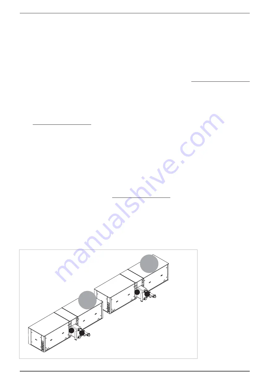
KEY
1 Evaporator (plate-type exchangers)
2 Water filter 1 x circuit SUPPLIED
3 Flow
switch
NB
In addition to the filter, victaulic and
welded pipes are provided
The drawings represent only examples
of the machine hydraulic circuit
Circuit 1°
Circuit 2°
1
1
2
2
40
INRLPY. 02.10 4086916_01
Summary of Contents for NRL
Page 2: ......


