background image

13

E

nglish

MDIH

DESCRIPTION OF THE UNIT

DESCRIPTION OF COMPONENTS

The EXCI series conditioners are constituted by an indoor air 
treatment unit and by an outdoor unit to be connected to each 
other by means or refrigeration and electrical lines.
They are available in three sizes with different capacities in 
heat-pump version able to perform both summer cooling and 
the winter heating.
All the EXCI units have an "A" class energy effi ciency in cooling 
mode and "A" class energy effi ciency in heating mode.
The inverter device permits great energy saving and the 
optimisation of the environmental conditions, the required 
temperature is reached more quickly than systems without and 
inverter.

The units are characterised by very quiet operation and great 
reliability.
The indoor unit has a maintenance charge (nitrogen).
The control device (accessory TL2I) consists of an infra-red 


remote control and a wall receiver, it provides full control 
functions.
The EXCI series conditioners are able to meet climate-control 
requirements in all environments thanks to the versatility of the 
indoor units made for horizontal or upright installation, with 
channels (the series is available with a large range of plenum 
chambers and dedicated fi ttings for every size) or with casings 
(accessories).

The indoor unit is made of galvanised steel sheet. At the back 
there are holes to fi x the equipment to the wall, at the front there 
is a steel sheet panel enclosing the fan unit. The trays for the 
collection of the condensate are fi tted with special drainage 
features, it is possible to attach the channels for the renewal of 
the air in the environment and/or for delivery to a next door 
room, to the unit.
The unit contains:
– the heat exchanger coil with copper pipes and turbulenced 
type fi ns made of aluminium locked in place by means of the 
mechanical expansion of the pipes;
– the fan unit on anti-vibration mountings with double-suction 
centrifugal fans, coupled directly to a three-speed motor with 
thermal protection.
The fact that the tray and inspectable fan volutes may be removed 
(only by adequately skilled technicians) allows the internal 
components to be cleaned thoroughly, which is particularly 
important for installations in crowded areas or areas requiring 

high hygiene standards.
The units are confi gured in the factory in such a way as to have 
the rated air fl ow and null residual static pressure. To get the 
maximum useful static pressure for the channelling again with 
the rated air fl ow make the connections as shown in the 
following wiring diagrams;
–the microprocessor type control unit with dip switches to be set 
during installation in accordance with the confi guration of the 
machine and the accessories;
–fi ltering unit that can be easily removed in material that can be 
regenerated can be cleaned by washing;
–intake temperature probe.
–defrosting device (only for the versions with heat pumps) is 
controlled by means of a probe on the interior coil and the 
environment air probe that are controlled by the electronic card 
which turns the defrosting circuit on and off. It permits the 
proper functioning of the device with high yields down to an 
outside temperature of  -10°C.

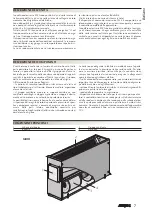
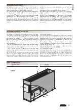
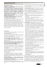
MAIN COMPONENTS 

1 Electronic 

card

2 Coil 

3 Fan 

unit

4 Air 

fi lter

2

3

4

1

Summary of Contents for ixci R410A

Page 1: ...ol heat pump with inverter for channelled installation Climatiseur split system pompe à chaleur avec Inverter pour installations gainables Klimaanlage mit Splitsystem und Wärmepumpe mit Invertertechnologie für kanalisierte Installation Climatizador split system bomba de calor con Inverter para instalaciones canalizadas ISO 9001 Cert n 0128 4 A Efficienza energetica Energy efficiency Efficacité éne...

Page 2: ...zione EUROVENT I prodotti interessati figurano nella Guida EUROVENT dei Prodotti Certificati Aermec is partecipating in the EUROVENT Certification Programme Products are as listed in the EUROVENT Directory of Certified Products Aermec partecipe au Programme de Certification EUROVENT Les produits figurent dans l Annuaire EUROVENT des Produits Certifiés Aermec ist am Zertifikations Programm EUROVENT...

Page 3: ... deve essere installato esclusivamente in abbinamento con le unità CWI_H di nostra produzione Solo rispettando tali abbinamenti é valida la seguente dichiarazione DICHIARAZIONE DI CONFORMITÀ Noi firmatari della presente dichiariamo sotto la nostra esclusiva responsabilità che la macchina in oggetto è conforme a quanto prescritto dalle seguenti Direttive Direttiva macchine 98 37 CEE Direttiva bassa...

Page 4: ... wieviele Geräte stapelbar sind Apilamiento observe en el embalaje la posición de la flecha para saber cuántos equipos pueden apilarse NON calpestare Do NOT trample NE PAS marcher sur cet emballage Nicht betreten NO pisar NON trasportare la macchina da soli se il suo peso supera i 35 Kg DO NOT handle the machine alone if its weight is over 35 Kg NE PAS transporter tout seul l appareil si son poids...

Page 5: ...elettriche ed elettroniche Criteri di scelta Limiti di funzionamento Descrizione dell unità Componenti principali Descrizione dei componenti Dati dimensionali Linee frigorifere Installazione dell unità Dati elettrici Schemi elettrici Servizio assistenza Tecnica Italia 6 7 8 9 10 35 INDICE ...

Page 6: ...di isolamento dell impianto elettrico Prova della continuità dei conduttori di protezione La manutenzione straordinaria consiste in una serie di operazioni complesse che comportano lo smontaggio del condizionatore o dei suoi componenti grazie alle quali si ripristina la condizione di massima efficienza nel funzionamento del condizionatore Interventi Pulizia interna frequenza annuale o prima di lun...

Page 7: ...ichi è possibile raccordare all unità i canali per il rinnovo dell aria ambiente e o per la mandata in un locale attiguo All interno dell unità sono alloggiati la batteria di scambio termico con tubi di rame ed alette di tipo turbolenziato di alluminio bloccate medinte espansione meccanica dei tubi il gruppo ventilante montato su supporti antivibranti con ventilatori centrifughi a doppia aspirazio...

Page 8: ...rifere 15 m 15 m 15 m H Massimo dislivello tra unità interna ed esterna 7 m 10 m 10 m Reintegro carica gas refrigrante R410A 15 g m 15 g m 15 g m Per lunghezza linee superiore a 7 5 m 7 5 m 7 5 m LINEE FRIGORIFERE DATI DIMENSIONALI mm A D P B 9 x 20 40 4 388 F G N E C M H L EXC 070 I EXC 090 I EXC 120 I Mod EXC 070 I EXC 090 I EXC 120 I A 457 457 457 B 592 823 1043 C 216 216 216 D 440 671 891 E 45...

Page 9: ...1 Tenere sigillata ogni estremità aperta delle tubazioni con un tappo o altro fino a che non sia completato l allacciamento 2 Prestare molta attenzione durante l allacciamento delle tubazioni affinchè acqua sporcizia etc non entrino nelle tubazioni e nell impianto 3 Le tubazioni allacciate all unità interna ed esterna devono essere nuove Lo spessore richiesto per le tubazioni è di 0 8mm o più 4 Ut...

Page 10: ...6 23OV 50Hz N N L PE M 1 3 2 N L SD MV IG MA RO GR BL BL F 3 15A SA 1 N RO RO MA EXC I 11 4 1 2 inverter single split 2 4 6 8 L G S 12 04 N4 11 CN4 CN5 BZ1 CN80 2 N 1 OUTDOOR UNIT CWI H P VI EXTERNAL CONTACT BL TL2I SEZ A SEZ A Collegamenti da eseguire in loco Accessorio Componenti non forniti BL BLU GR GRIGIO MA MARRONE NE NERO RO ROSSO VI VIOLA CN Connettore IG Interruttore magnetotermico L Line...

Page 11: ... di apparecchiature elettriche ed elettroniche Selection criteria Operating limits Description of the unit Main components Description of components Size data Refrigeration lines Installation Of the unit Electrical data Wiring diagrams TABLE OF CONTENTS 12 13 14 15 16 ...

Page 12: ... C R H 85 The EXCI conditioners must be powered with current 1 230 V 50Hz and have an earth connection the line voltage must anyway fall within a tolerance of 10 of the nominal value If the air conditioner unit is working in continuous cooling mode inside an environment where the relative humidity is high condensate might form on the air delivery Said condensate might be deposited on the floor and...

Page 13: ...cial drainage features it is possible to attach the channels for the renewal of the air in the environment and or for delivery to a next door room to the unit The unit contains the heat exchanger coil with copper pipes and turbulenced type fins made of aluminium locked in place by means of the mechanical expansion of the pipes the fan unit on anti vibration mountings with double suction centrifuga...

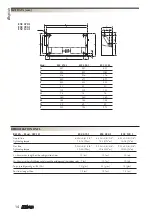
Page 14: ... Maximum length of the refrigeration lines 15 m 15 m 15 m H Maximum height difference between the outdoor and the indoor units 7 m 10 m 10 m Top up refrigerant gas R410A 15 g m 15 g m 15 g m For lines longer than 7 5 m 7 5 m 7 5 m A D P B 9 x 20 40 4 388 F G N E C M H L EXC 070 I EXC 090 I EXC 120 I Mod EXC 070 I EXC 090 I EXC 120 I A 457 457 457 B 592 823 1043 C 216 216 216 D 440 671 891 E 453 45...

Page 15: ...aled closed with a plug or similar until all connections have been made 2 Proceed with extreme caution while connecting the piping so that water dirt etc do not get into the pipes or the system 3 The pipes connected to the indoor and outdoor units must be new The required thickness for the pipes is 0 8 mm or more 4 Only use refrigerant that conforms with that already loaded in the outdoor unit whe...

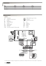
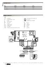
Page 16: ...V 50Hz N N L PE M 1 3 2 N L SD MV IG MA RO GR BL BL F 3 15A SA 1 N RO RO MA EXC I 11 4 1 2 inverter single split 2 4 6 8 L G S 12 04 N4 11 CN4 CN5 BZ1 CN80 2 N 1 OUTDOOR UNIT CWI H P VI EXTERNAL CONTACT BL TL2I SEZ A SEZ A Connections to be made on site Accessory Components not supplied BL BLUE GR GREY MA BROWN NE BLACK RO RED VI VIOLET CN Connector IG Magnetothermal switch L Line M Terminal strip...

Page 17: ...ctriques et électroniques Critères de choix Limites de fonctionnement Description de l unité Principaux composants Description des composants Données dimensionnelles Lignes frigorifiques Installation de l unité Données électriques Schémas électriques TABLE DES MATIÈRES 18 19 20 21 22 ...

Page 18: ...nsion de ligne doit de toute manière respecter une plage de tolérance de 10 par rapport à la valeur nominale Si le climatiseur fonctionne de façon continue en refroidissement dans un milieu où l humidité est relativement élevée de la condensation peut se former sur le refoulement de l air Cette condensation pourrait se déposer sur le sol et sur les objets déposés en dessous Le fonctionnement en ch...

Page 19: ...e de raccorder à l unité les gaines pour le renouvellement de l air ambiant et ou pour le soufflage dans une pièce voisine A l intérieur de l unité se trouvent la batterie d échange thermique avec les tuyaux de cuivre et les ailettes du type avec turbulence d aluminium bloquées par expansion mécanique des tubes le groupe de ventilation monté sur des supports antivibratoires avec des ventilateurs c...

Page 20: ... 40 N m L Longueur maximum lignes frigorifiques 15 m 15 m 15 m H Dénivellement maximum entre unité intérieure et extérieure 7 m 10 m 10 m Top up refrigerant gas R410A 15 g m 15 g m 15 g m Pour longueur lignes supérieures à 7 5 m 7 5 m 7 5 m A D P B 9 x 20 40 4 388 F G N E C M H L EXC 070 I EXC 090 I EXC 120 I Mod EXC 070 I EXC 090 I EXC 120 I A 457 457 457 B 592 823 1043 C 216 216 216 D 440 671 89...

Page 21: ...é ouverte des tubes avec un bouchon ou autre jusqu à ce que le branchement soit terminé 2 Faire très attention pendant le branchement des tubes afin d éviter que de l eau de la saleté etc entrent dans les tubes et dans l installation 3 Les tubes branchés à l unité intérieure et extérieure doivent être neufs Ils doivent avoir 0 8mm d épaisseur ou même davantage 4 Pour rajouter du réfrigérant dans l...

Page 22: ...N N L PE M 1 3 2 N L SD MV IG MA RO GR BL BL F 3 15A SA 1 N RO RO MA EXC I 11 4 1 2 inverter single split 2 4 6 8 L G S 12 04 N4 11 CN4 CN5 BZ1 CN80 2 N 1 OUTDOOR UNIT CWI H P VI EXTERNAL CONTACT BL TL2I SEZ A SEZ A Branchements à effectuer sur les lieux Accessoire Composants non fournis BL BLEU GR GRIS MA MARRON NE NOIR RO ROUGE VI VIOLET CN connecteur IG Interrupteur magnétothermique L Ligne M B...

Page 23: ...n elektrischen und elektronischen Geräten Auswahlkriterien Grenzwerte für den Gerätebetrieb Beschreibung der Einheit Hauptkomponenten Beschreibung der Komponenten Abmessungen Kühlleitungen Installation der Einheit Daten zur Elektrik Schaltpläne INDEX 24 25 26 27 28 ...

Page 24: ...eses Handbuchs nachschlagen WARTUNG AUSWAHLKRITERIEN GRENZWERTE FÜR DEN GERÄTEBETRIEB Bei der Wahl des geeigneten Montageortes ist zu berücksichtigen dass die Grenzen der maximalen und minimalen Raumtemperatur Ta 0 C Ta 45 C einzuhalten sind R F 85 Die Klimageräte EXCI werden mit Strom mit 1 230 V 50 Hz gespeist und sind geerdet die Netzspannung muss jedoch innerhalb des Toleranzbereichs von 10 be...

Page 25: ... Die Kondensat Sammelwannen sind mit eigenen Abflüssenausgestattet esbestehtdieMöglichkeit entsprechende Leitungen für die Frischluftzufuhr bzw für die Luftleitung in einen angrenzenden Raum an die Einheit anzuschließen In der Einheit befinden sich Der Wärmetauscher mit Kupferrohren undTurbolenz Lamellen aus Aluminium die durch die mechanische Dehnung der Rohre fixiert sind Die Lüftungseinheit mon...

Page 26: ...ximale Länge der Kühlleitungen 15 m 15 m 15 m H Maximaler Höhenunterschied zwischen Innen und Außeneinheit 7 m 10 m 10 m Nachfüllen der Kühlgasladung R410A 15 g m 15 g m 15 g m Bei Leitungslängen von über 7 5 m 7 5 m 7 5 m A D P B 9 x 20 40 4 388 F G N E C M H L EXC 070 I EXC 090 I EXC 120 I Mod EXC 070 I EXC 090 I EXC 120 I A 457 457 457 B 592 823 1043 C 216 216 216 D 440 671 891 E 453 453 453 F ...

Page 27: ...ist mit einer Verschlusskappe oder ähnlichem versiegelt halten 2 Besonders während des Anschlusses der Leitungen darauf achten dass kein Wasser Schmutz usw in die Leitungen und in die Anlage eindringt 3 Die an die Innen und Außeneinheit angeschlossenen Leitungen müssen neu sein Die für die Leitungen geforderte Stärke beträgt mindestens 0 8 mm 4 Zum Nachfüllen nur Kältemittel verwenden das mit dem ...

Page 28: ... TR1 RY6 23OV 50Hz N N L PE M 1 3 2 N L SD MV IG MA RO GR BL BL F 3 15A SA 1 N RO RO MA EXC I 11 4 1 2 inverter single split 2 4 6 8 L G S 12 04 N4 11 CN4 CN5 BZ1 CN80 2 N 1 OUTDOOR UNIT CWI H P VI EXTERNAL CONTACT BL TL2I SEZ A SEZ A Vor Ort auszuführende Anschlüsse Zubehör Nicht gelieferte Teile BL BLAU GR GRAU MA BRAUN NE SCHWARZ RO ROT VI VIOLETT CN Stecker IG Schutzschalter L Leitung M Klemml...

Page 29: ...aratos eléctricos y electrónicos Criterios de elección Límites de funcionamiento Descripción de la unidad Componentes principales Descripción de los componentes Dimensiones Líneas de refrigeración Instalación de la unidad Datos eléctricos Esquemas eléctricos ÍNDICE 30 31 32 33 34 ...

Page 30: ...riente 1 230V 50Hz y deben conectarse con conexión a tierra en cualquier caso la tensión de línea debe mantenerse dentro de los límites de tolerancia de 10 respecto al valor nominal Si el acondicionador funciona de forma constante en frío en el interior de un ambiente con elevada humedad relativa podría formarse agua de condensación en la boca de ventilación Dicha agua de condensación podría depos...

Page 31: ... evacuación Se pueden conectar a la unidad los canales que renuevan el aire ambiente y o para mandarlo a un local contiguo Dentro de la unidad se encuentran la batería de intercambio térmico con tubos de cobre y aletas de perfil turbolenciado de aluminio bloqueadas mediante la expansión mecánica de los tubos el grupo de ventilación montado en un soporte antivibración con ventiladores centrífugos d...

Page 32: ...ngitud máxima líneas de refrigeración 15 m 15 m 15 m H Desnivel máximo entre unidades interna y externa 7 m 10 m 10 m Reintegro carga gas de refrigeración R410A 15 g m 15 g m 15 g m Para longitud de líneas superior a 7 5 m 7 5 m 7 5 m A D P B 9 x 20 40 4 388 F G N E C M H L EXC 070 I EXC 090 I EXC 120 I Mod EXC 070 I EXC 090 I EXC 120 I A 457 457 457 B 592 823 1043 C 216 216 216 D 440 671 891 E 45...

Page 33: ...uberías con un tapón u otros hasta que se haya completado la conexión 2 Preste mucha atención durante la conexión de las tuberías para que no entre en las mismas ni en la instalación agua suciedad etc 3 Las tuberías conectadas a las unidades interna y externa deben ser nuevas Las tuberías deben tener un grosor de 0 8mm o más 4 Recargue con gas refrigerante la instalación utilizando sólo el mismo t...

Page 34: ...z N N L PE M 1 3 2 N L SD MV IG MA RO GR BL BL F 3 15A SA 1 N RO RO MA EXC I 11 4 1 2 inverter single split 2 4 6 8 L G S 12 04 N4 11 CN4 CN5 BZ1 CN80 2 N 1 OUTDOOR UNIT CWI H P VI EXTERNAL CONTACT BL TL2I SEZ A SEZ A Conexiones que deben realizarse in situ Accesorio Componentes no suministrados BL AZUL GR GRIS MA MARRÓN NE NEGRO RO ROJO VI VIOLETA CN Conector IG Interruptor magnetotérmico L Línea...

Page 35: ...uol del Fosso FE 0532 978 450 FORLÌ RAVENNA RIMINI ALPI GIUSEPPE Via N Copernico 100 47100 Forlì 0543 725 589 MODENA Nord CLIMASERVICE di Golinelli Stefano Via Per Modena 18 E 41034 Finale Emilia MO 053 592 156 MODENA Sud AERSAT s n c di Leggio M Lolli S Piazza Beccadori 19 41057 Spilamberto MO 059 782 908 PARMA ALFATERMICA s n c Galbano Biondo Via Mantova 161 43100 Parma 0521 776 771 PIACENZA MOR...

Page 36: ...es behält sich Aermec S p A vor in der Produktion Änderungen und Verbesserungen ohne Ankündigung dur chzuführen ILos datos técnicos indicados en la presente documentación no son vinculantes Aermec S p A se reserva el derecho de realizar en cualquier momento las modificaciones que estime necesarias para mejorar el producto Aermec partecipa al Programma di Certificazione EUROVENT I prodotti interess...

Reviews: