


06/05/13
AERCO International, Inc.
•
100 Oritani Dr.
•
Blauvelt, NY 10913
•
Ph: 800-526- 0288
Page
1
of
112
GF-115-C
OMM-0084_0D
.
Revised: 06/05/2013
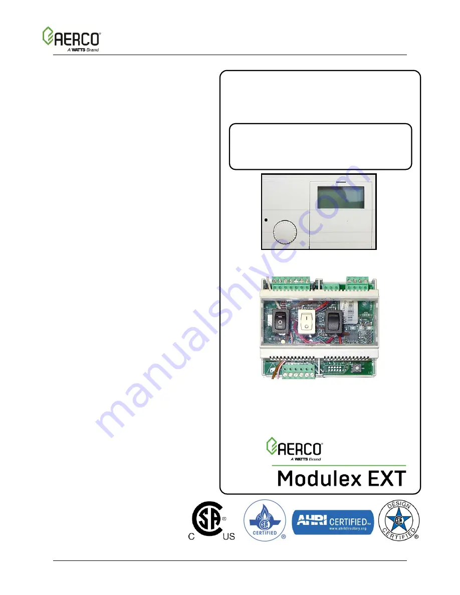
E8 Controller and BCM
For
Modulex MLX & EXT Boilers
For Modulating, Condensing,
Hot Water Boiler Models:
•
MLX-303
•
MLX-454
•
MLX-606
•
MLX-757
•
MLX-909
•
MLX-1060
•
EXT 321
•
EXT 481
•
EXT 641
•
EXT 802
•
EXT 962
•
EXT 1123
•
EXT 1530
•
EXT 1912
•
EXT 2295
•
EXT 2677
•
EXT 3060
E8 Controller for MLX & EXT Series Boilers
Boiler Communications Module (BCM)
for MLX and EXT Series Boilers
USER MANUAL
Installation, Operation, and Maintenance


