AEQ XPEAK User Manual Download Page 30


AEQ

 XPEAK


IP Intercom System 


30 

3.2. Xpeak_BP menus. 


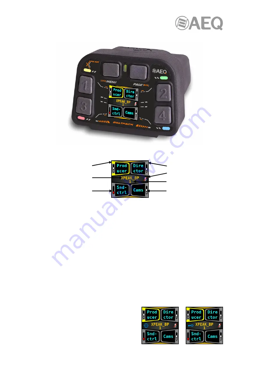
On the operation screen of the unit, the display shows the following information: 


In the example above, all 4 keys are configured and the destinations associated with each key 
are  "Producer",  "Director",  "Snd-ctrl"  and  "Cams"  respectively. When  programming  a  key  from 
the  "AEQ  Xpeak"  application,  a  label  is  automatically  associated  with  it  according  to  the 
destination and the type of command: if we use the default label it appears written in white on 
the display, while if the text is changed appears in cyan. 


Regarding  the  color  of  the  keys,  green  indicates  that  the  key  has  been  pressed  on  the 
equipment itself and red indicates that communication has been established (unidirectional if it's 
flashing  or bidirectional  if it remains fixed). The color yellow  would indicate the combination of 
green and red, as follows: 


Fixed yellow: fixed green (pressed key) + fixed red (bidirectional communication). 


Blinking  between  green  and  yellow:  fixed  green  (pressed  key)  +  blinking  red 
(unidirectional communication). 


Fixed  green:  the  key  has  been  pressed  but  there  is  no  communication  with  the 
destination device. 


In the example above, the fist key is  yellow because it's been pressed on the equipment itself 
and bidirectional communication is established; that key would be red if the communication had 
been established from the remote device (fixed red when that communication was bidirectional 
and blinking when it was unidirectional). 


Finally,  at  the  left  of  the  device  name,  the  icon  of 
the  globe  may  also  appear  (indicates  that  there  is 
an  Internet  connection)  or  the  icon  of  the  key 
(indicates  that  the  unit  is  connected  to  the  AEQ 
VPN service): 


Activated key 


Device name 


Muted audio 


Deactivated key 


Muted microphone 


Page 


Reception volume 

Summary of Contents for XPEAK

Page 1: ...NUAL ED 07 22 V 1 7 12 04 2023 Firmware Versions Xpeak_R Xpeak_D Xpeak_BP CPU 2 2 5 or higher Xpeak_IF CPU 2 2 5 AoIP CPU 4 2 5 1 or higher Xplorer CPU 1 00 022 or higher Software Versions Xpeak 1 0 5 or higher Xpeak Virtual 1 0 2 or higher ...

Page 2: ...17 2 3 1 Front panel description 17 2 3 2 Other elements 18 2 3 3 Headset connector 18 2 3 4 Description of the Charging Terminal 19 2 4 Physical description of Xpeak_IF I O interface 20 2 4 1 Front panel description 20 2 4 2 Rear panel description 20 3 MENUS DESCRIPTION 22 3 1 Xpeak_R and Xpeak_D menus 22 3 1 1 Xpeak menu 24 3 1 1 1 Mute Key option 24 3 1 1 2 Dev Name option 24 3 1 1 3 Key Auto o...

Page 3: ... 2 2 Screen organization and preliminary definitions 61 5 2 3 Menus 62 5 2 3 1 Upper left menu Upper line with drop down menus 62 5 2 3 2 Upper left menu Lower line with icons 66 5 2 3 3 Upper right window menu 72 5 2 4 Software operation 74 5 2 4 1 Configuration of network parameters 74 5 2 4 2 Scheme background image selection 74 5 2 4 3 New devices groups and families 76 5 2 4 4 Working on the ...

Page 4: ...AEQ XPEAK IP Intercom System 4 6 FIRMWARE UPGRADE 98 7 A E Q GUARANTEE 102 8 ADDITIONAL INFORMATION 103 ...

Page 5: ...es with access to Internet or to a WAN they will all connect On the other hand the system does not need a matrix the elements of the system form a network of P2P peer to peer devices with Ethernet virtualization Further an intercom system is a mission critical tool that must neither fail nor be vulnerable to cyber attacks Therefore Xpeak includes advanced security features such as access control r...

Page 6: ...y and best features Rack and desktop equipment will use 4 way levers instead of keys for easier operation of basic functions Listen Talk and adjust the receive volume Additional equipment is included to provide analog digital and IP audio inputs and outputs to the system The equipment has been designed to be very cost effective with optimum performance Great audio quality HD Voice up to 7 kHz with...

Page 7: ... is compatible with Xplorer wireless system were keys 8 in stationary devices and 4 in the beltpacks are programmed with the same flexibility found in AEQ KROMA matrix based systems Max capacity of this matrix is up to 28 panels Audio quality is 7 kHz HD voice o Party Line HD mode A Party Line system is configured on Xpeak panels and beltpacks offering 4 channels and compatible with Xplorer wirele...

Page 8: ...ngle switch port GPIOs 10 pin mini Hartmann connector includes 2 opto coupled GPIs and 2 GPOs one external circuit power pin and ground Bluetooth The equipment incorporates a Bluetooth connection as an audio interface with a telephone or headset Front audio o Gooseneck electret microphone supplied with the panel o Internal speaker that develops 84dB SPL 1 m USB Audio o Front USB for headset o Rear...

Page 9: ...onnector for headset Bluetooth for audio interface with a telephone or headset Ethernet network connection RJ45 connector with interlocking PoE power supply GPO One GPO output through two pins Mechanics Anti shock plastic beltpack Dimensions and weight Front Width 92 mm Height 70 mm Depth 130 mm Weight 327 gr Functional Keys pagination 2 pages total 8 virtual keys Echo cancellation Group LEDs The ...

Page 10: ...echanics Anti shock plastic beltpack Dimensions and weight Front Width 92 mm Height 70 mm Depth 130 mm Weight 365 gr Functional Xplorer terminals can be ordered on demand ready with capability to operate in XPeak systems with the following functional characteristics Internal programming of the Xpeak functionality On screen display of Xpeak status and menus 2 pages of keys total 8 virtual keys SDN ...

Page 11: ...ervoltage or battery disconnection The charger receives continuous power current from an external power supply Devices can be charged both being on and off if the device is on the approximate current charge level is displayed on its screen it s recommended to wait until the upper LED of the charging terminal turns on green to consider the device fully charged Technical specifications Charging term...

Page 12: ...ween Dante audio and encoded audio Control GPIOs Mini Hartmann connectors include 4 opto coupled GPIs and 4 GPOs external power pin and ground 1 54 color TFT screen Allows information such as IP address audio presence and status to be displayed Encoder and menu key to navigate the user interface and facilitate configuration and status viewing Dimensions and weight Front Width 482 6 mm Height 44 5 ...

Page 13: ...ription 1 Microphone connector This connector is valid exclusively for the provided condenser microphone 2 USB connector for optional headset A type connector compatible with any USB standard headset When connected the local microphone and integrated loudspeaker are deactivated 3 8 x 2 axis lever keys Each one has an associated RGB LED 4 1 54 TFT Color screens 5 Rotary encoder with push button Dur...

Page 14: ...al panels can be connected in Daisy Chain using a single switch port Any of the two Ethernet connectors allow for these connections as the panel includes an internal switch Detail of ETHERNET connectors Physically both are RJ45 10 100 1000 connectors with the pinout described below RJ45 connector pinout 3 USB type B connector for connection to a PC Digital USB audio input output on a B type female...

Page 15: ...on t require any specific driver IMPORTANT NOTE Shielded cable is required to make the connection between the USB port and PC 4 2 GPIOs multi pin connector A 10 pin 3 5mm pitch pluggable connector can be found A screw terminal male block is provided with the unit As seen from the rear and from left to right the and pins for each of the two GPIs are available Then a 5V supply output and ground and ...

Page 16: ...cates the status of each key grey inactive key green active key red blinking red or yellow different conversation states 9 Key label indicating the remote peer name or group 10 External access symbol active TRV system is open to remote correspondents 11 Panel name label showing its name within the Intercom system 12 Page number In systems based on virtual or physical matrix pages are identified by...

Page 17: ... with a long press 4 Four programmable keys for direct access to communication channels or channel selection in Party Line mode engraved with the numbers 1 2 3 and 4 The function of each key at any time is related to the information indicated in the nearest screen quadrant Short press activates or deactivates the communication latch mode Long press activates the communication while the key is pres...

Page 18: ...eath In order to turn off the unit press and keep pressed for 5 seconds 15 Belt anchors to be used as a shoulder strap with tape or with a carabiner 16 Belt hook 17 Charging connector 2 3 3 Headset connector Micro headphone headsets are connected to a male Tini QG connector located at the bottom of the unit The input stage for the headset s microphone is designed to be used with electret capsules ...

Page 19: ...linking this slot should NOT be used there is some supply problem and it may damage the device An upper LED that indicates charging activity o it s off when there s no device in the slot o it turns on red when the device is charging o and green when charging is finished o if it turns off while charging it indicates a problem during this process such as charge precharge time exceeded overvoltage or...

Page 20: ...udio device that is displayed as USB Audio CODEC Audio towards the intercom system can be sent from any audio playback software as if it was an external professional grade soundcard Also audio from the Intercom can be recorded on the PC using any audio recording software This audio comes from the channels which have been routed to the corresponding output This virtual sound card is plug play under...

Page 21: ... pin 3 5mm pitch pluggable connector can be found A screw terminal male block is provided with the unit As seen from the rear and from left to right the and pins for each of the 4 GPIs are available Then a 5V supply output and ground and then the and pins for each of the 4 GPOs 5V supply is provided to bias external devices such as transistors closing the GPO contacts Connecting a 4K7 ohm resistor...

Page 22: ...d red bidirectional communication Blinking between green and yellow fixed green pressed key blinking red unidirectional communication Fixed green the key has been pressed but there is no communication with the destination device In the following example there are just 3 keys configured and the destinations associated with each of them are Cam1 Cam2 and Cam3 respectively In addition the first and s...

Page 23: ...operate the menus press the PAGE MENU to go back press the encoder button to accept and turn the encoder knob to navigate throughout the menu options The left screen shows the different available menu options The first menu level includes the following five options By turning the encoder we can select any of them Press the encoder button to enter the selected option Pressing PAGE MENU takes you ba...

Page 24: ...irector and Snd ctrl Once the key o keys are selected you can return to previous menu by long pressing the PAGE MENU key 3 1 1 2 Dev Name option Allows us to change the device s name It supports a maximum of 8 characters When accessing this option the current name s first character is selected By pressing the encoder the cursor will be highlighted in red By turning the encoder the character can be...

Page 25: ...us screen where the key appears reflected in the third field which is merely informative in the example key 1 of the first page has been selected Pg 1 Key 1 Next step is to define the destination that this key will provide access to by means of the Select Target option Once selected it will appears reflected in the fourth field which is also only informative Finally you have to confirm that the co...

Page 26: ...is Kroma G711 EasyNET mode Panels integrate into the EasyNET 4 channel Party Line system compatible with earlier panels and Xplorer Audio quality is Kroma G711 EasyNET G722 mode Panels integrate into a 4 channel Party Line system compatible with Xplorer wireless system Audio quality is 7 kHz HD 3 1 3 Connection menu By pressing the encoder when the Connection option is visible on the screen you en...

Page 27: ...menu entry is highlighted pressing the encoder button checks or disables this option Mask Configures the mask of the subnet the panel is connected to Its max length is 32 bits up to 255 255 255 255 If you are not used to this format remember that 24 bits is equivalent to mask 255 255 255 0 16 bits is equivalent to mask 255 255 0 0 8 bits is equivalent to mask 255 0 0 0 The procedure to change the ...

Page 28: ...ernet connection and VPN indicates if the unit is connected to the AEQ VPN service fields appear About Allows us to check the operative system version the firmware version the serial number and unit s type RACK when it s a Xpeak_R and DESKTOP when it s a Xpeak_D 3 1 6 Menu differences in other operating modes 3 1 6 1 All modes except Xpeak Xpeak mode is the only one that supports families characte...

Page 29: ...lecting it by pressing the encoder the displays return to the operation screen where the key whose communication you want to cut off is selected Then the key will be disabled both in the source panel of the communication and in the destination panel Mute Key The functionality is the same as defined in section 3 1 1 1 3 1 6 3 EasyNET and EasyNET G722 modes They are 4 channel Party Line modes so in ...

Page 30: ...ixed The color yellow would indicate the combination of green and red as follows Fixed yellow fixed green pressed key fixed red bidirectional communication Blinking between green and yellow fixed green pressed key blinking red unidirectional communication Fixed green the key has been pressed but there is no communication with the destination device In the example above the fist key is yellow becau...

Page 31: ... operation screen long pressing the LOCK MENU key allows us to lock the keyboard A new long press of this key allows us to unlock the keyboard 3 2 1 Xpeak menu This is the most used menu during operation as it shows very important functions for online operation Press the PAGE MUTE key when the Xpeak option is visible on screen to enter this first menu The different options in this menu are highlig...

Page 32: ...arded by means of the Cancel option associated to key 3 By pressing the LOCK MENU key once we ll go back to the main screen of the Xpeak menu and two more pressings take us to the operation screen 3 2 1 3 Key Auto option Allows you to enable the auto discovery mode When a Xpeak device discovers another device on the network and has no keys programmed to communicate with it a key is automatically p...

Page 33: ... the Select Key option by pressing the PAGE MUTE key the operation screen appears and you can select the key by pressing it you can select a key of page 1 or press PAGE MUTE and select one of page 2 Once the key is selected it automatically returns to the previous screen where the key appears reflected in the second field which is merely informative in the example key 2 of the first page has been ...

Page 34: ...n red By turning the right encoder the number can be substituted by another Numbers from 0 to 9 can be chosen the figure that can be configured in each octet is limited between 0 and 255 By pressing the PAGE MUTE key again the cursor is highlighted back in white so by turning the right encoder we can move to another number of the IP address By pressing that key again the cursor is highlighted in r...

Page 35: ... when the Info option is visible on the screen you enter this menu that allows us to check the main configuration parameters of the beltpack and that presents the following options Network Allows us to check the network configuration of the beltpack The fields that appear are MAC address IP address mask gateway and DNS In section 3 2 3 the way to configure all these parameters is detailed In addit...

Page 36: ...these operating modes the first menu shows two specific functions Reject It allows to cut off a communication If a remote panel has established communication with our panel and we want to hang up that call this option should be used When selecting it by pressing the PAGE MUTE key the display returns to the operation screen where the key whose communication you want to cut off is selected Then the ...

Page 37: ... taking us to the device s setup menus Some frequently used options can be found while other are for configuration Long pressing the MENU key allows us to lock unlock the keyboard The screen shows the different available menu options The first menu level includes the following five options By turning any of the two encoders we can select any of them Press the SELECT key to enter the selected optio...

Page 38: ...ro headphone icon with a red crossing bar appears indicating its inactivity However headphones still remain active so the configured conversations can be heard Name Allows us to change the device s name It supports a maximum of 8 characters When accessing this option the current name s last character is selected By turning any of the two encoders the character can be substituted by another The key...

Page 39: ... On the other hand if no valid system is found this LED will blink green 3 3 3 CONNECTION menu This is a configuration menu that allows the user to select the parameters of the Wi Fi network the unit will connect to When the CONNECTION option is highlighted in green by pressing the SELECT key this third menu is accessed Any of the two encoders can be used to navigate through the 6 options of the m...

Page 40: ...etween uppercase letters lowercase letters numbers and special characters By pressing OK right function key the typed name is validated By pressing CANCEL left function key changes are ignored and the former name will remain Password Use this option to type or modify the password of the WiFi network that the terminal has to connect to The procedure is the same as for creating or editing the name H...

Page 41: ...ress must be confirmed by pressing OK or changes can be discarded by pressing CANCEL o Mask prefix Configures the mask of the subnet the beltpack is connected to Its max length is 32 bits up to 255 255 255 255 By turning any of the two encoders the number can be modified By pressing the key 4 RESET you can return to the initial value If you are not used to this format remember that 24 bits is equi...

Page 42: ...ELECT key allows to enter the selected one The available options are Screen Allows to configure the following display parameters o Brightness When this option is selected an auxiliary screen appears where the screen brightness can be modified using any of the two encoders within a range from 1 low to 7 high in order to suit the operating environment ambient light Press the OK key when the adjusted...

Page 43: ...call is received It turns off again when the Timeout expires Keyboard Configures the usage of the left and right function keys Their default configuration is as follows Left Key short pressing MENU Left Key long pressing LOCK Right Key short pressing PAGE Right Key long pressing MUTE However a different configuration may be more adequate depending on the particular operating way Press the SELECT k...

Page 44: ...g the SELECT key this fifth menu is accessed Any of the two encoders can be used to navigate through the 3 options of the menu and the SELECT key allows to enter the selected one The available options are Battery Provides detailed information about the battery status Network Allows us to check the network configuration of the beltpack ...

Page 45: ...ection indication when the device does not have an Internet connection appears when it has an Internet connection Internet appears and when it s connected to VPN VPN appears Version Allows us to check the operative system version the firmware version the user interface version and the serial number 3 3 6 Menu differences in other operating modes 3 3 6 1 All modes except Xpeak Xpeak mode is the onl...

Page 46: ...be heard ROLES Shows the list of the user roles that can be assigned to the unit if they re configured in the matrix and enabled in the unit for the operator to select the desired one REJECT Rejects an incoming call REPLAY Reproduces the last received message in case it couldn t be heard properly first time or maybe the user didn t pay attention to it 3 3 6 3 EasyNET and EasyNET G722 modes They ar...

Page 47: ...ions The first menu level includes the following three options By turning the encoder we can select any of them Press the encoder button to enter the selected option Pressing MENU BACK takes you back in the menu and repeating the key press takes you back to the operation screen 3 4 1 Connection menu By pressing the encoder when the Connection option is visible on the screen you enter this menu whi...

Page 48: ...lighted pressing the encoder button checks or disables this option Mask Configures the mask of the subnet the interface is connected to Its max length is 32 bits up to 255 255 255 255 If you are not used to this format remember that 24 bits is equivalent to mask 255 255 255 0 16 bits is equivalent to mask 255 255 0 0 8 bits is equivalent to mask 255 0 0 0 The procedure to change the mask and confi...

Page 49: ...k Allows us to check the network configuration of the interface The fields that appear are MAC address IP address mask gateway and DNS In section 3 4 1 the way to configure all these parameters is detailed In addition the Inet indicates if there is an Internet connection and VPN indicates if the unit is connected to the AEQ VPN service fields appear About Allows us to check the operative system ve...

Page 50: ...s required see section 4 1 The auto run USB key furnished with the Xpeak devices contains the executable file that installs the application Installing it is simply a matter of executing this file and following the on screen instructions as they come up Once the software is installed by default in C Program files Xpeak Virtual you can start it up by double clicking the icon displayed on the desktop...

Page 51: ...AEQ XPEAK IP Intercom System 51 Next the initial screen of the application appears ...

Page 52: ... on the initial screen When you press the Enter License button a window will appear allowing you to introduce the key You must copy the content of the Code field and send it to AEQ in order to generate the associated license and send it back to you you must paste it in the License field The OK button allows you to confirm the key and when it s correct activate it In that case in the Settings windo...

Page 53: ...screen appears and after it the initial screen In case its license is already activated and their buttons have been configured from the Xpeak application it will look something like this The default position of the window is in the center of the main monitor screen if there are several or near the upper left corner if the resolution is very low By clicking with the mouse anywhere that is not a but...

Page 54: ...ve formats to which it can be resized to adapt the occupation on the screen to the needs of the user to share the monitor with other applications In order to do this just place the mouse in a corner of the window click and drag In any of the available formats the elements that appear reflected in the application are the following ...

Page 55: ...k On the other hand in the third row there are 4 buttons that allow you to activate a Talk with each of the 4 channels of a Xpeak_IF interface The name of the virtual panel that appears at the bottom left is the name that will identify the Xpeak Virtual application in the system It s possible to edit it from the application settings window see section 4 2 2 or from the Xpeak application see sectio...

Page 56: ... on the remote device Fixed orange Indicates that communication has been established between the 2 devices involved and a Talk and a Listen are being executed bidirectional communication It remains this way if the button has been pressed on the Xpeak Virtual application It s the combination of fixed green and fixed red status Blinking between green and orange Indicates that communication has been ...

Page 57: ...ication version is shown at the top of the Settings window Below is the internal identifier of the application in the system Next the Change Name button allows you to change the name that identifies the Xpeak Virtual application in the system Pressing on it enables the edit box on the right and disables everything else allowing the name to be modified ...

Page 58: ...s you to configure the network parameters of the application There are two sections in that window Local network Allows us to select the local network LAN interface that the application will use Remote network Allows us to select the remote network VPN interface that the application will use When selecting any of them the IP and MAC addresses corresponding to that interface will appear in the lowe...

Page 59: ...d that automatic programming is not carried out 4 2 3 Use of the application without mouse In case the mouse doesn t work or you want to speed up certain actions via keyboard the application can be used using the keyboard With the tabulator you can focus on the different elements of the application This selection of elements has an specific order and goes in a circle so that the final element retu...

Page 60: ...l the system and select sources and destinations of AoIP Dante audio signals Dante Controller application must be used Please consult the AEQ AoIP user s manual for more information 5 2 AEQ Xpeak Xpeak configuration and control software 5 2 1 Introduction AEQ Xpeak application is the configuration and control software for the Xpeak devices The auto run USB key furnished with the devices contains t...

Page 61: ...r quadrants Upper left Devices and groups list Lower left Families list Upper right System diagram display area Lower right Selected device or group display area It is possible to resize the height of each of the quadrants at both sides using the mouse Place the cursor in the lower and upper windows delimiting area where the cursor icon changes in order to modify the size of the two upper and two ...

Page 62: ...on opens the window that allows you to configure the network parameters of the application There are two sections in that window Local network Allows us to select the local network LAN interface that the application will use Remote network Allows us to select the remote network VPN interface that the application will use When selecting any of them the IP and MAC addresses corresponding to that int...

Page 63: ... check the status of the devices that appear in the list on the left It shows the status of the devices white when visible on the network and red when not name type serial number internal identifier in the case of Xpeak Virtual firmware version software in the case of Xpeak Virtual IP address and whether it s connected by VPN indicated by a green marked button The list of devices is updated as the...

Page 64: ...device s key or lever Delete device Allows us to eliminate a device Delete group Allows us to eliminate a group of user terminals Delete family Allows us to eliminate the selected user terminals families Delete button Allows us to eliminate the function assigned to a certain device s key or lever Snooping Allows us to put the application in place of a selected panel to check its operation Audio te...

Page 65: ... background image or plan for the upper right quadrant Delete device from scheme Deletes the selected device from the upper right quadrant window These functions are duplicated in the menu bar located at the right side of the operation screen see section 5 2 3 3 of this manual The Help drop down menu allows us to access to the window that shows the application version by selecting the About Xpeak ...

Page 66: ...New group Allows us to create a new group of user terminals The new group s default name starts with a capital G followed by seven digits This name can be replaced by any other alphanumeric name of course New family Allows us to create a new family of user terminals The new group s default name starts with a capital F followed by seven digits This name can be replaced by any other alphanumeric nam...

Page 67: ...d changes to allow edition Edit button After a device has been selected appears then in the lower right quadrant when we place the cursor over one of its buttons it is highlighted in yellow and when we press it in orange If now we press the icon it changed from grey to orange or double clicking on the button a window pops up in order to assign commands or functions to the button The buttons or cro...

Page 68: ... the upwards activation and the other one for the downwards activation whose programming is accessed by placing the cursor on the upper or lower half of the button respectively The Target field allows us to select the device the key or lever is going to interact with The Label field allows us to configure the name that will be assigned to the key which is usually referenced to the Target device Wh...

Page 69: ...list and in the scheme After a device is selected the icon changes from grey to orange when clicking on this icon those configurations are deleted also interrupting all active communications at that moment that device was involved in That s why double confirmation is required Delete group After a group is selected the icon changes from grey to orange when clicking on this icon the group is deleted...

Page 70: ...hanges from grey to orange when clicking on this icon the family is deleted also removing the signaling associated to that family on the devices buttons Double confirmation is required It is possible to select several families by keeping pressed the Ctrl key when making the selection ...

Page 71: ...d deletes the button In both options double confirmation is required Snooping After a device is selected the icon changes from grey to orange when clicking on this icon it changes to yellow the PC where the application is installed will replicate the selected device in terms of audio that is everything that the physical device is listening to will also be heard on the PC the audio of all the devic...

Page 72: ...plication gives access to the following options As in the rest of the menus each option will only be available when it appears marked in orange Open scheme Allows us to open the window to select the background image or plan for the upper right quadrant This option is also available in the Scheme menu Show all configuration When clicking on this option all communication flows are depicted in the di...

Page 73: ... case the focus will remain centered on the point of the image where we have clicked Delete image from scheme When clicking on this icon the background image or plan for the upper right quadrant is deleted Delete device from scheme After a device is selected in the scheme the icon changes from grey to orange and the device is highlighted in orange when clicking on this icon the device is deleted f...

Page 74: ...k LAN interface and the remote network VPN interface that the application will use 5 2 4 2 Scheme background image selection If there is no selected background image a grey background will be applied by default in the upper right quadrant Using the Open scheme option of the Scheme drop down menu keyboard shortcut O a dialogue shows up where the user can choose an image in bmp jpg png or tif format...

Page 75: ... preserving its original aspect ratio referred to its larger dimension and if necessary filled with a grey color so the largest dimension reaches the minimum size When an image has been selected it won t be necessary to select the same one each time the application is started ...

Page 76: ...The addition of devices is only possible automatically when the application receives an internal message generated by the system publishing their discovery Group addition is automatically performed with the reception of a internal message indicating which devices belong to that group It can also be done manually using the New group option of the Edit drop down menu keyboard shortcut G in this case...

Page 77: ...ere is any modification name buttons configuration etc it is updated in the corresponding device screen as well as in the devices list If the group or family the device is associated to is also modified the corresponding group or family window will be updated Besides if the devices that a key or lever activates communication with are shown in the scheme a line indicating the path between those dev...

Page 78: ...sent in the network its name in the list and scheme will turn red to signal that condition As soon as communication is re established with it the corresponding name will be displayed in white again When the configuration of a key or lever includes a device or group which doesn t correspond with any already configured it is created in the list as an unknown device or group and its name will be its ...

Page 79: ...scheme In order to place devices in the scheme of the upper right quadrant click on one of the devices in the list and keeping the mouse pressed drag it to the desired position within the scheme Once in the scheme the device can be relocated just in the same way If in addition that device has established communication with others the lines indicating that connection in the scheme will also move ac...

Page 80: ...that appears When the name change procedure is complete it can be validated by clicking outside it or pressing the keyboard s Enter key then the editor is closed and the device s name is changed in all places showing it By double clicking on a device in the scheme outside its name area it will be represented in the device view at the lower right quadrant 5 2 4 5 Devices or groups detail display In...

Page 81: ... name by right clicking on the family s name and selecting the Edit name option that appears The editor that appears has a white edition box used only for name modification In other words only the device group or family name can be altered but not its type that is displayed before by a symbol Once the name modification is completed it can be validated by clicking outside it or using the keyboard s...

Page 82: ...AEQ XPEAK IP Intercom System 82 Xpeak_BP Xplorer Xpeak_IF Xpeak Virtual Xpeak_R Xpeak_D ...

Page 83: ...on any of the devices to include it marked in light grey or remove it from the group marked in dark grey Once the group has been configured pressing the Validate button will save the changes made The name of the group that is being displayed appears in the upper left area of that quadrant and after clicking on it it can be modified by double clicking on it pressing the F2 key using the Edit name o...

Page 84: ...mode is usually assigned to the upper position and Talk in PTT mode to the lower one Once a button is selected you can also change the selection by moving through the buttons of the device using the Tab key or the arrow keys When right clicking on a button it s activated just as we were activating it in the physical device so it changes from OFF to ON status and it changes to blue color If the but...

Page 85: ...ey function 4 Remote One Way Source Target Label and Key function 5 Remote Two Ways Source Target Label and Key function 6 GP Out Target GPO Label and Key function The Target drop down menu allows us to select the system device or group that will be the destination with which the device we are configuring will interact to which it will talk listen or talk and listen In the case of the Remote One W...

Page 86: ...target in uppercase Example BP1 BP2 5 Remote Two Ways First three letters of the source in uppercase dual arrow and first three letters of the target in uppercase Example BP1 BP2 6 GP Out All uppercase same as Talk Listen Example XPEAK_BP In the case of the Xpeak_R and Xpeak_D panels on whose levers two functions can be programmed the label is always associated with the function corresponding to p...

Page 87: ...mouse pressed drag it until you drop it on the desired button the button changes to yellow when placed over it also appearing a square with a and it changes to orange when you release the mouse This way the configuration of one button is moved to the other In case that one or both buttons is active highlighted in blue that activation will be voided when this transfer operation is performed In orde...

Page 88: ...r a Xpeak_IF since they are the only devices that have GPIs 2 in the case of the panels and 4 in the case of the interface Pressing one of these tabs displays the window that allows you to configure the GPI Select the command to be executed when the corresponding GPI is activated on the device in the Command drop down menu The available commands are the same as those detailed for the buttons and i...

Page 89: ...ppears below Target allows you to select the GPO that will be activated on the target when the corresponding GPI is activated on the configured device In this case only Xpeak_R Xpeak_D Xpeak_BP and Xpeak_IF type devices appear in the Target list which are the ones that have GPOs 5 2 4 8 Editing the members and color of a family In order to change the devices and the color associated to a family do...

Page 90: ...on appears in the upper part of the window and by clicking on it it is possible to edit it Once all changes are made if the button OK is clicked on modifications are saved On the other hand clicking on the Cancel button discards 5 2 4 9 Communication flows scheme Lines indicating communication flows between pairs of devices appear on the scheme in the upper right quadrant according to the configur...

Page 91: ... that is the PC where the application is installed will replicate the selected device in terms of audio that is everything that the physical device is listening to will also be heard on the PC the audio of all the devices with which a listen command is active and the audio from the PC audio played or from the microphone depending on how the PC is configured will replace the audio from the physical...

Page 92: ...se of the application without mouse In case the mouse doesn t work or you want to speed up certain actions via keyboard the application can be used using the keyboard for all options except drag and drop With the tabulator you can focus on the different elements of the application This selection of elements has an specific order and goes in a circle so that the final element returns to the initial...

Page 93: ...ticated in the Xpeak Cloud Server in charge of keeping a record of all the devices belonging to the same Virtual Network The server allows visibility between all the devices that are registered in the same virtual network and also routes through it the audio from the panels that are part of different local networks Xpeak units leave the factory registered to work in a virtual network when indicate...

Page 94: ...ork On the Network settings window different IP addresses for Local network and Remote network will be shown The remote network should be configured Take note that the configuration PC has at least two IP addresses the local one and the remote one In the AEQ Xpeak software you must specify in File Network settings in the Remote network section the name of the virtual network or tunnel in this exam...

Page 95: ...ected to the Internet as if they were in the same location as the local devices As mentioned the configuration file for the WireGuard client software is provided by AEQ with the systems when purchasing the remote virtual network license If you don t have this file and need to work in different locations please contact AEQ support via email support aeq es 5 3 3 2 Local panels configuration The devi...

Page 96: ... will be connected For other types of remote environments or even residential environments there may be a switch connected to the router in that case it s in that switch where the Xpeak devices will be connected In residential environments the router usually has a DHCP server automatic IP addresses However in other remote environments with a router independent from the switch it may be the case of...

Page 97: ...e to access the Internet 5 3 4 Configuration of communication keys between panels In order to customize by means of the AEQ Xpeak software the panel keys that are going to operate remotely they can be preconfigured by previously connecting the panel to the local network where the rest of the units are and programming the panel keys Setting can also be customized from the remote location For this i...

Page 98: ... module whose firmware is upgraded by means of the DANTE Firmware Update Manager application consult the AEQ AoIP user s manual The procedure for upgrading the MICRO module firmware is as follows 1 Check the IP address associated with the unit s Ethernet interface in the Network option of the unit s Info menu see sections 3 1 5 and 3 2 5 of this manual 2 Open the web browser Google Chrome for exam...

Page 99: ...AEQ XPEAK IP Intercom System 99 4 Then the upgrading process starts 5 Once the upgrade bar reaches 100 the module restarting process begins ...

Page 100: ...out option of the unit s Info menu see sections 3 1 5 and 3 2 5 of this manual As indicated in point 2 of this section in order to access the upgrading screen the proxy in the web browser must be disabled In order to do that you have to access to Settings of the browser and go to Advanced System Open your computer s proxy settings ...

Page 101: ...e the 2 indicated boxes in the following window Warning You should not act on the system during the upgrading process and you must never turn off the equipment since this action may deprogram the module that you are trying to upgrade which would entail sending that unit in order to be repaired ...

Page 102: ...mply with these conditions will not be accepted 3 AEQ will at its own cost repair the faulty product once returned including the necessary labour to carry out such repair whenever the failure is caused by defects of the materials design or workmanship The repair will be carried out in any of the AEQ authorized Technical Service Centre This guarantee does not include the freight charges of the prod...

Page 103: ...iate radio frequency energy and if not installed and used in accordance with the instruction manual may cause harmful interference to radio communications Operation of this equipment in a residential area is likely to cause harmful interference in which case the user will be required to correct the interference at his own expense Dante is a trademark of Audinate Pty Ltd Product includes license fr...

Reviews: