


86
Updating Dash Firmware
As part of the continuing development process, from time to time new versions of the AEM Dash firmware will be
released with new DashDesign installers. To upload the new firmware:
·
Firmware files are installed to the \Documents\AEM\DashDesign\Firmware folder.
·
Connect the color display to your PC using the USB link..
·
Select
Tools | Upload Firmware
. Select the firmware (.bin) file from the location above.
·
The upload process starts. Do not switch the display off during the upload process as this may corrupt the
firmware.
·
Once the upload process has finished, unplug the USB cable to reboot the display.
The Setup Editor
The AEM DashDesign Setup Editor is used to configure the non-visual objects of a setup i.e.
Outputs
and
Operations
. Some outputs use more than one input depending on the operation used. The setup editor is accessed
by selecting
Setup | Display...
.
Each page of the editor has
Insert
and
Delete
buttons which are used to insert or delete an item in that tab. The
following sections describe the various operation types available and how they are used to make an output.
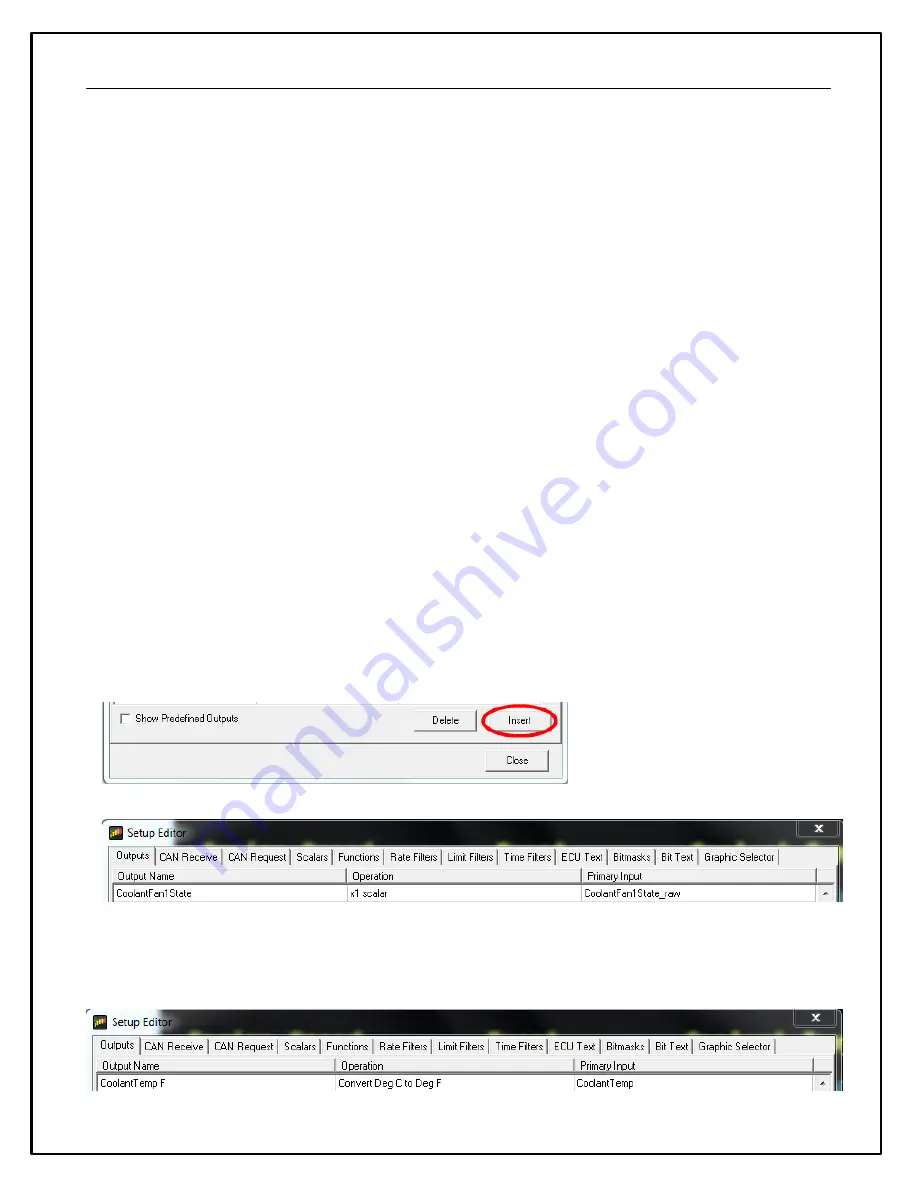
Outputs
Outputs are values, texts or graphics that are used by gauges or other outputs. The output that it passes is
determined by the operation that it uses.
To set up a new output:
·
Click the Insert button in the Outputs tab.
·
Enter the name of the new output. This should describe what the output actually generates.
·
Select the operation to be used by the output from the drop-down list.
·
Select the input from the drop down list.
The example above shows the basic use of a x1 scalar. It uses a raw input and passes it through as itself with the
opportunity to change the name.
CoolantFan1State = (CoolantFan1State_raw)*(1)
Summary of Contents for CD-5 Carbon
Page 12: ...12 Dash Mechanical and Mounting CD 7 Mechanical ...
Page 13: ...13 CD 5 Mechanical ...
Page 14: ...14 CD 7F Mechanical ...
Page 15: ...15 CD 5F Mechanical ...
Page 16: ...16 Drill Template Drill template prints to scale ...
Page 17: ...17 Dash Harness and Basic Wiring ...
Page 18: ...18 Optional OBDII and Power Cable Kits ...
Page 31: ...31 System Schematic ...
Page 39: ...39 IMAGE NOT TO SCALE ...
Page 41: ...41 System Schematic ...
Page 51: ...51 CAN Transmit Rate Unit 1 50 Hz CAN Transmit Rate Unit 2 25 Hz ...
Page 58: ...58 ID Type User Configurable 11 29 bits Termination None Ohm DLC 8 Bytes ...
Page 64: ...64 ...
Page 65: ...65 ...
Page 66: ...66 ...
Page 67: ...67 ...