background image

Service Information 5-1

5

Service Information 

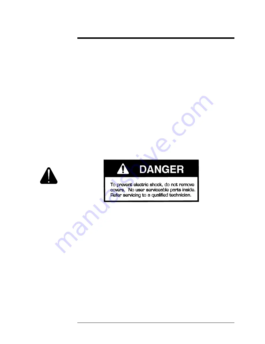
This amplifier has sophisticated circuitry, which should only be serviced by a fully 
trained technician. 

5.1 Qualified Service 

AE T

ECHRON 

I

NC

.

 will provide service to the original purchaser of each new 

AE 

T

ECHRON

LVC 608/623/2016

 for a period of one (1) year from the date of 

purchase if all conditions of the warranty have been met. When you notify us of 
your need for warranty service, we will give you an authorization to return the 
product for service.  

Warranty work can only be performed at our authorized service centers or at our 
factory. Expenses in remedying the defect will be borne by 

AE T

ECHRO

N

 INC

.

including one-way surface freight shipping costs within the United States. 
(Purchaser must bear the expense of shipping the product between any foreign 
country and the port of entry in the United States and all taxes, duties, and other 
customs fees for such foreign shipments.)  

5.1.1 Factory Service 

To obtain factory service, write a letter describing as fully as you can the problem 
and send it along with your proof of purchase and the defective unit. For warranty 
service, we will pay for ground shipping back to you if you are within the 
continental United States. After repair and thorough testing the factory will return 
your serviced unit via truck. Please contact us if other arrangements are required.  

Summary of Contents for LVC2016

Page 1: ...AE TECHRON INC Technical Manual LVC608 LVC623 and LVC2016 Power Supply Amplifiers ...

Page 2: ......

Page 3: ...RON INC LVC608 LVC623 LVC2016 Power Supply Amplifiers Technical Manual AE TECHRON INC 2002 2507 Warren St Elkhart IN 46516 U S A Phone 574 295 9495 Fax 574 295 9496 E Mail Sales aetechron com www aetechron com ...

Page 4: ...s from the standard LVC 608 input card in the following ways a Each channel will accept a balanced or unbalanced input on a 1 4 inch phone jack or a balanced three pin female XLR on the back panel these are wired in parallel for each channel b It does not have voltage and current monitor outputs c It supports only controlled voltage operation controlled current operation is not available 2 Page 1 ...

Page 5: ...ust bear the expense of shipping the product between any foreign country and the port of entry in the United States and all taxes duties and other customs fees for such foreign shipments HOW TO OBTAIN WARRANTY SERVICE When you notify us of your need for warranty service we will give you an authorization to return the product for service All components must be shipped in a factory pack or equivalen...

Page 6: ......

Page 7: ...a Revision Control Revision Date 0 Initial Release November 2002 A May 2004 Page Number Revision Number Corrections on 1 5 1 6 1 7 A ...

Page 8: ......

Page 9: ... 4 3 Parallel Mono Hookup 2 10 2 4 4 Connecting Power 2 12 Section 3 Applications 3 1 Introduction 3 1 3 2 Amplifier Capability 3 2 3 2 1 Series Mono Application 3 2 3 2 2 Parallel Mono Application 3 2 3 3 Plug in Modules 3 3 3 4 AC Power Applications 3 4 3 4 1 AC Power Draw and Thermal Dissipation 3 4 Section 4 Principles of Operation 4 1 Overview 4 1 4 2 Features 4 2 4 3 Front End Operation 4 3 ...

Page 10: ......

Page 11: ...s except in specific circumstances Review this material before installing or operating the amplifier AE TECHRON is committed to continuous product improvement Technical progress may result in minor variations between this manual and a particular unit Any significant changes or customizations will be reflected in revisions of this manual Customers are encouraged to promptly add any additional infor...

Page 12: ...ovides full information on the amplifiers including service procedures Safety should be your primary concern as you use these products and follow these procedures Special hazard alert instructions appear throughout this manual Note the following examples NOTE A Note represents information which needs special emphasis but does not represent a hazard ...

Page 13: ...que output block which combines heavy duty binding bolts and dual banana connectors Other features include the ability to Switch from Dual Mode to Bridge Mono or Parallel Mono Mode with a 3 position slide switch Select three different gain values for either channel with two more 3 position slide switches located inside the input compartment The LVC 608 623 2016 Series use the latest technology and...

Page 14: ...requency Response 0 1 dB from 20 Hz to 20 kHz at 1 watt Phase Response 10 from 10 Hz to 20 kHz at 1 watt Signal to Noise Ratio At 26 dB gain better than 105 dB A weighted below full output Total Harmonic Distortion THD 0 05 from 20 Hz to 1 kHz increasing linearly to 0 1 at 20 kHz at full output I M Distortion 0 05 from 410 milliwatts to full output at 26 dB gain with an 8 ohm load Slew Rate 13V pe...

Page 15: ...93 34 2 8 225 42 4 225 42 4 210 41 16 129 45 5 129 45 5 129 45 5 Two Channel Bridged Max voltage 40mSec Burst 5 Minute Continuous Sine 1 Hour Continuous Sine Ohms Watts Volts Watts Volts Watts Volts 4 750 54 7 625 50 50 14 2 8 655 72 4 586 68 5 255 45 2 16 450 84 9 402 80 2 402 80 2 Two Channels Paralleled Max Current 40mSec Burst 5 Minute Continuous Sine 1 Hour Continuous Sine Ohms Watts Volts Wa...

Page 16: ...9 38 2 89 37 8 2 89 2 37 78 Bridged Mono Maximum Voltage 40mSec 5 Minutes Continuous Ohms Watts Volts Amps Watts Volts Amps Watts Amps Volts 4 0 0 0 583 48 3 12 538 12 46 4 8 0 0 0 431 58 7 7 431 7 58 7 16 0 0 0 289 68 4 290 4 68 1 Parallel Mono Maximum Current 40mSec 5 Minutes Continuous Ohms Watts Volts Amps Watts Volts Amps Watts Amps Volts 1 552 23 5 24 520 23 22 8 2 420 29 14 418 28 9 14 418 ...

Page 17: ... 406 80 6 5 406 5 80 6 Bridged Mono Maximum Voltage 40mSec 5 Minutes Continuous Ohms Watts Volts Amps Watts Volts Amps Watts Amps Volts 4 2070 91 23 8 1585 113 14 1602 113 2 14 114 4 30 2 16 1035 129 8 995 126 2 8 994 8 126 1 Parallel Mono Maximum Current 40mSec 5 Minutes Continuous Ohms Watts Volts Amps Watts Volts Amps Watts Amps Volts 2 1605 57 28 114 15 1 8 114 8 15 1 4 1035 64 16 995 63 1 16 ...

Page 18: ...utput Impedance Less than 10 milliohms is series with less than 2 microhenries Connectors Inputs Euro style screw terminals will accept up to 16 gauge bare wire Outputs Unique output bus with dual banana jacks on 3 4 inch centers and high current ring or spade lug barrier connectors AC Line Standard plug Construction Material Black splatter coat steel chassis with specially designed flow through f...

Page 19: ...l B Level Control The output level for each channel is set with these controls Each control has 31 detents for precise adjustment C Overload Indicators When a large input signal causes an input overload or output clipping these green indicators flash brightly with a 0 1 second hold otherwise they indicate the presence of a distortion free signal D Power Indicator This amber indicator lights when t...

Page 20: ...gh current output block is provided for output connection Its connectors accept banana plugs spade lugs or bare wire I Parallel Mono Stereo Bridge Mono This switch is used to select one of three output modes Parallel Mono Stereo or Bridge Mono J Gain Switches These three position switches are used to select a voltage gain of 20 70 or 140 gain for each channel K Input Plug in Module The versatility...

Page 21: ...connected to Pin 10 if an unbalanced input is desired Pins 9 and 11 are not active when amplifier is used in either mono mode 12 Ground pin for use with pins 13 14 and 15 13 Voltage monitor will have 1 20th of voltage at output of Channel 1 when operated in 2 channel or Parallel Mono mode and 1 40th of the voltage when operated in Bridged Mono mode Pin 13 is active in all modes of operation 14 Cur...

Page 22: ...ured at Pin 7 of U4 VR10 Adjusts DC offset of Channel 1 of amplifier measured at output of amplifier Should be adjusted if gain of amplifier is changed JMPCC1 CV Puts Channel 1 in Constant Voltage Mode CC Puts Channel 1 in Constant Current Mode CC or CV must be jumped for channel to operate CC1 Constant Current compensation 1 for Channel 1 connects C 23 and R55 CC2 Constant Current compensation 2 ...

Page 23: ...Adjusts DC offset of Channel 2 of amplifier measured at output of amplifier Should be adjusted if gain of amplifier is changed JMPCC2 CV Puts Channel 2 in Constant Voltage Mode CC Puts Channel 2 in Constant Current Mode CC or CV must be jumped for channel to operate CC1 Constant Current compensation 1 for Channel 2 connects C24 and R53 CC2 Constant Current compensation 2 for Channel 2 connects C26...

Page 24: ...ground loops If other devices attached to the amplifier inputs and outputs are mounted in an electrically common rack and are likewise internally chassis ground joined ground loops may be formed When this occurs isolate the most appropriate units from the rack so a loop is not formed Another source of ground loop trouble is the third wire of the AC main connector Only one piece of equipment in a s...

Page 25: ...nect the box to the main board 2 Dial in the calculated values 3 Connect load to output at output and sampled common terminals 4 Input square wave at highest frequency used in application with generator set for minimum amplitude 5 Connect oscilloscope to current monitor with ground 6 Enable the amplifier from Standby to Ready and observe oscilloscope 7 If the system is stable no oscillations incre...

Page 26: ...stems expect to decrease the value of R109 in series systems by 1 2 for 2 units and increase the value double for 2 units in parallel systems Compensation Waveforms From Left to Right Box 1 Optimum Compensation Box 2 Increase R109 Box 3 Decrease R109 Box 4 Increase C104 Box 1 Box 2 Box 3 Box 4 ...

Page 27: ... for ANY signs of damage a Make written notes of any damage for future reference b If damage is found notify the transportation company immediately c Save the shipping carton and packing materials as evidence of damage for the shipper s inspection d If severe damage is apparent DO NOT proceed until a representative of the shipping company is present 2 Uncrate unpack the amplifier 3 Save the packin...

Page 28: ...d 19 inch 48 3 cm rack mounting and stack mounting without a cabinet For optimum cooling and rack support multiple units should be stacked directly on top of each other To reduce the risk of ELECTRIC SHOCK or FIRE HAZARD DO NOT expose the LVC 608 623 2016 to rain or moisture ...

Page 29: ...r to Section 3 Applications for detailed information on thermal dissipation When mounting the amplifier in a rack cabinet the back wall of the rack should be at least 3 inches 7 6 cm away from the back of the amplifier chassis as shown below If your rack has a door that could block airflow to the amplifier s air intakes you must provide adequate airflow by installing a grille in the door or by pre...

Page 30: ...the top of the rack so that air inside the cabinet is drawn out the back Option 2 previous page If the air supply is unusually dusty you might want to pre filter it using commercial furnace filters to prevent rapid loading of the unit s own air filters When needed the unit s filters can be cleaned with mild dish detergent and water You may want to allow at least two additional inches of depth for ...

Page 31: ...o short circuit Do not use connectors that can be plugged into AC power receptacles 4 Keep unbalanced input cables as short as possible Avoid lengths greater than 10 feet 5 Do not run signal input cables together with high level wiring such as load output wires or AC cords lowers most hum and noise 6 Do not short the ground lead of an output cable to the input signal ground Oscillations may result...

Page 32: ...it 10 seconds for the power supply to discharge 3 Slide the Dual Mono switch to the center position 4 Connect the output wiring as shown below The high current output block has three sets of output connectors per channel so multiple loads can be easily connected Two sets accept banana plugs while the third set accepts spade lugs or bare wire Observe correct load polarity and be very careful not to...

Page 33: ...Installation 2 7 ...

Page 34: ...ace the back of the amplifier NOTE Both outputs receive the signal from the Channel 1 input with the output of Channel 2 inverted so it can be bridged with the Channel 1 output AND NOTE The Channel 2 input and level controls are disconnected in Bridge Mono Mode A signal feeding Channel 2 will have no effect on the output 4 Connect the load across the Channel 1 and 2 positive terminals 5 Attach the...

Page 35: ...Installation 2 9 ...

Page 36: ...l 2 input Both outputs will now receive the signal from the Channel 1 input NOTE The Channel 2 input and level controls are disconnected in Parallel Mono Mode A signal feeding Channel 2 will have no effect on the output To complete connections 5 Install a jumper wire between the positive outputs of Channel 1 and 2 that is at least 14 gauge in size 6 Connect the load to the output of Channel 1 as s...

Page 37: ...Installation 2 11 ...

Page 38: ...itry For example do not exceed a line voltage of 133V AC for units set up for 120V AC operation All specifications in this manual were measured using 120V AC 60 Hz power mains unless otherwise noted Specifications are derived using a peak main voltage equal to the true peak of a 120V RMS sine wave with all available channels fully loaded Performance variations can occur at other AC main voltages a...

Page 39: ...ion This section is included for customers who may need to customize the LVC 608 623 2016 for a new application For these users this section provides general theory and guidance This section assumes significant competence on your part in terms of amplifier systems electronic components and generally sound electronic working practices You are encouraged to contact AE TECHRON for assistance with any...

Page 40: ...to Channel 2 may be made in either mono mode The Channel 2 level control should be turned down counter clockwise fully in either mono mode NOTE Gain Switch for Channel 2 makes no difference 3 2 1 Bridge Mono Applications Bridge Mono is intended for loads of 4 ohms or greater The feedback loop for Channel 1 also drives the input to Channel 2 in this mono mode The input to Channel 2 is however inver...

Page 41: ...s is an excellent way to customize the amplifier for different applications in a relatively short amount of time The LVC 608 623 2016 amplifiers are equipped with an input module inside the back panel The modules install easily as shown below ...

Page 42: ... provide a realistic and reliable depiction of the amplifier The following assumptions were made The amplifier s available Channels are loaded and full standard 1 kHz power is being delivered Quiescent power draw is 90 watts Quiescent heat dissipation equals 105 btu hr at 90 watts Here are the equations used to calculate the data presented on the following page The quiescent power draw of 90 watts...

Page 43: ...e temperature becomes excessive and just by the minimum amount necessary This patented approach is called ODEP or Output Device Emulation Protection It maximizes the available output power and eliminates overheating the major cause of output device failure The amplifier is protected from all common hazards that plague high power amplifiers including shorted open or mismatched loads overloaded powe...

Page 44: ...lize numerous innovations including grounded bridge and ODEP technologies Cooling techniques make use of the what is essentially air conditioner technology Air flows bottom to top and front to side Air flows a short distance across a wide heat sink Output transistors are of the metal can type rather than plastic case This allows for a significantly higher thermal margin for the given voltage and c...

Page 45: ...e VGS where gain is determined by the position of the Sensitivity Switch and level is determined by the level control VGS is an inverting stage with the input being fed to its op amp stage Because gain after this stage is fixed at 26 dB factor of 20 greater amplifier sensitivity is achieved by controlling the ratio of feedback to input resistance 4 3 3 Error Amp The inverted output from the VGS is...

Page 46: ...ith equal gain They shift the audio from the 15V reference to VCC reference Their outputs drive their respective LVA Also tied into the Voltage Translator inputs are ODEP limiting transistors and control protection transistors The ODEP transistors steal drive as dictated by the ODEP circuitry discussed later The control protection transistors act as switches to totally shunt audio to ground during...

Page 47: ...r factory Expenses in remedying the defect will be borne by AE TECHRON INC including one way surface freight shipping costs within the United States Purchaser must bear the expense of shipping the product between any foreign country and the port of entry in the United States and all taxes duties and other customs fees for such foreign shipments 5 1 1 Factory Service To obtain factory service write...

Page 48: ... wooden crates any other packing material will not be sufficient to withstand the stress of shipping Do not use loose small size packing materials 3 Do Not ship the unit in any kind of cabinet wood or metal Ignoring this warning may result in extensive damage to the unit and the cabinet Accessories are not needed do not send the instruction manual cables or other hardware 4 If you have any questio...

Reviews: