Principles of Operation 4-3
4.3 Front End Operation
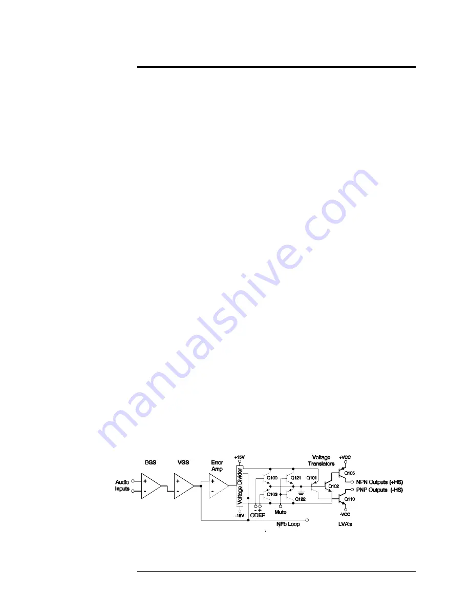
The front end is comprised of three stages: Balanced Gain Stage (BGS), Variable
Gain Stage (VGS), and the Error Amp.
Figure 4.1
shows a simplified diagram of
a typical front end with voltage amplification stages.
4.3.1 Balanced Gain Stage (BGS)
Input to
the amplifier is balanced. The shield may be isolated from chassis
ground by an RC network to interrupt ground loops via the Ground Lift Switch.
The non- inverting (hot) side of the balanced input is fed to the non-inverting
input of the first op-amp stage. The inverting (negative) side of the balanced input
is fed to the inverting input of the first op-amp stage. A potentiometer is provided
for common mode rejection adjustment. Electrically, the BGS is at unity gain. The
BGS is a non-inverting stage. It's output is delivered to the Variable Gain Stage.
4.3.2 Variable Gain Stage (VGS)
From the output of the BGS, the signal goes to the VGS where gain is determined
by the position of the Sensitivity Switch, and level is determined by the level
control. VGS is an inverting stage with the input being fed to its op-amp stage.
Because gain after this stage is fixed at 26 dB (factor of 20), greater amplifier
sensitivity is achieved by controlling the ratio of feedback to input resistance.
4.3.3 Error Amp
The inverted output from the VGS is fed to the non-inverting input of the Error
Amp op-amp stage through an AC coupling capacitor and input resistor.
Amplifier output is fed back via the negative feedback (NFb) loop resistor. The
ratio of feedback resistor to input resistor fixes gain from the Error Amp input to
the output of the amplifier at 26 dB. Diodes prevent overdriving the Error Amp.
Because the Error Amp amplifies the difference between input and output signals,
any difference in the two waveforms will produce a near open loop gain condition
which in turn results in high peak output voltage. The output of the Error Amp,
called the Error Signal (ES) drives the Voltage Translators.
Figure 4-1 Typical Amplifier Front End and Voltage Amplification Stages
Summary of Contents for LVC2016
Page 1: ...AE TECHRON INC Technical Manual LVC608 LVC623 and LVC2016 Power Supply Amplifiers ...
Page 2: ......
Page 6: ......
Page 8: ......
Page 10: ......
Page 33: ...Installation 2 7 ...
Page 35: ...Installation 2 9 ...
Page 37: ...Installation 2 11 ...


