background image


2-2. Setup the UPS 
Step 1: UPS input connection 

Plug the UPS into a two-pole, three-wire, grounded receptacle only. Avoid using extension 
cords.   


For 208/220/230/240VAC models:


The power cord is supplied in the UPS package.


For 110/115/120/127VAC models: The power cord is attached to the UPS. The input 
plug is a NEMA 5-15P for 1K, 1KL, 1.5K and 1.5KL models, NEMA 5-20P for 2K and 2KL 
models.     

Note:


For Low voltage models

: Check if the site wiring fault indicator lights up in LCD 

panel. It will be illuminated when the UPS is plugged into an improperly wired utility power 
outlet (Refer to Troubleshooting section). 
 

Step 2: UPS output connection 


For socket-type outputs, there two kinds of outputs: programmable outlets and 
general outlets. Please connect non-critical devices to the programmable outlets and 
critical devices to the general outlets. During power failure, you may extend the 
backup time to critical devices by setting shorter backup time for non-critical devices.   


For terminal-type input or outputs, please follow below steps for the wiring 
configuration: 

a) Remove the small cover of the terminal block 
b) Suggest using AWG14 or 2.1mm

2

 power cords. Suggest using WG12-10 or 

3.3mm

2

-5.3mm

2

 power cords for NEMA type. 

c) Upon completion of the wiring configuration, please check whether the wires are 

securely affixed. 

d) Put the small cover back to the rear panel. 


Step 3: Communication connection 
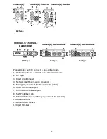
Communication port: 

USB port                            RS-232 port                  Intelligent slot 


To allow for unattended UPS shutdown/start-up and status monitoring, connect the 
communication cable one end to the USB/RS-232 port and the other to the communication 
port of your PC. With the monitoring software installed, you can schedule UPS 
shutdown/start-up and monitor UPS status through PC. 
 
The UPS is equipped with intelligent slot perfect for either SNMP or AS400 card. When 
installing either SNMP or AS400 card in the UPS, it will provide advanced communication 
and monitoring options.   
 

PS. USB port and RS-232 port can’t work at the same time.   


Step 4: Network connection 

Network/Fax/Phone surge port


Connect a single modem/phone/fax line into surge-protected “IN” outlet on the back panel 
of the UPS unit. Connect from “OUT” outlet to the equipment with another 
modem/fax/phone line cable.


Summary of Contents for TOPV 1500

Page 1: ...Top Vision UPS User Manual TOPV1000 TOPV 1500 TOPV 2000 TOPV 3000 Online UPS Uninterruptible Power Supply System...

Page 2: ...3 2 Installation and setup 4 2 1 Rear panel view 4 2 2 Setup the UPS 6 3 Operations 9 3 1 Button operation 9 3 2 LCD Panel 9 3 3 Audible Alarm 11 3 4 LCD display wordings index 11 3 5 UPS Setting 11...

Page 3: ...er them Do not connect domestic appliances such as hair dryers to UPS output sockets The UPS can be operated by any individuals with no previous experience Connect the UPS system only to an earthed sh...

Page 4: ...must be kept well away from the batteries Caution risk of electric shock The battery circuit is not isolated from the input voltage Hazardous voltages may occur between the battery terminals and the...

Page 5: ...itical loads 1 Output receptacles connect to mission critical loads 2 AC input 3 Input circuit breaker 4 Network Fax Modem surge protection 5 Emergency power off function connector EPO 6 USB communica...

Page 6: ...ow steps for the wiring configuration a Remove the small cover of the terminal block b Suggest using AWG14 or 2 1mm2 power cords Suggest using WG12 10 or 3 3mm2 5 3mm2 power cords for NEMA type c Upon...

Page 7: ...off the UPS in battery mode UPS will be in standby mode under power normal or transfer to Bypass mode if the Bypass enable setting by pressing this button Confirm selection key Press this button to co...

Page 8: ...bled Output Battery voltage information Indicates the output voltage frequency or battery voltage Vac output voltage Vdc battery voltage Hz frequency Load information Indicates the load level by 0 25...

Page 9: ...put voltage or frequency or battery voltage Vac Input voltage Vdc battery voltage Hz input frequency 3 3 Audible Alarm Battery Mode Sounding every 4 seconds Low Battery Sounding every second Overload...

Page 10: ...c 230 presents output voltage is 230Vac 240 presents output voltage is 240Vac For 110 150 120 127 VAC models you may choose the following output voltage 110 presents output voltage is 110Vac 115 prese...

Page 11: ...m 7V to 24V of the nominal voltage For 110 115 120 127 VAC models the setting voltage is from 3V to 12V of the nominal voltage 06 Bypass enable disable when UPS is off Interface Setting ENA Bypass ena...

Page 12: ...Programmable outlets enable DIS Programmable outlets disable 09 Programmable outlets setting Interface Setting 0 999 setting the backup time limits in minutes from 0 999 for programmable outlets which...

Page 13: ...ry mode When the input voltage is beyond the acceptable range or power failure and alarm is sounding every 4 second UPS will backup power from battery Bypass mode When input voltage is within acceptab...

Page 14: ...cond Battery is not connected Sounding every second Over Charge Sounding every second Site wiring fault Sounding every second EPO enable Sounding every second Fan Failure Sounding every second Over te...

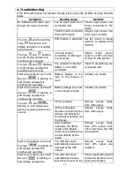
Page 15: ...ay and alarm is continuously sounding Battery voltage is too high or the charger is fault Contact your dealer Fault code is shown as 28 and the icon is lighting on LCD display and alarm is continuousl...

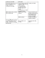
Page 16: ...The load is no longer supplied by power Contact your dealer Batteries are not fully charged Charge the batteries for at least 5 hours and then check capacity If the problem still persists consult you...

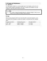
Page 17: ...ealer Storage Before storing charge the UPS 5 hours Store the UPS covered and upright in a cool dry location During storage recharge the battery in accordance with the following table Storage Temperat...

Page 18: ...erter to Bypass 4 ms Typical Waveform Batt Mode Pure Sinewave EFFICIENCY AC Mode 85 88 Battery Mode 83 BATTERY Battery Type 12 V 7 AH 12 V 9 AH 12 V 7 AH 12 V 9 AH Numbers 3 3 6 6 Recharge Time 4 hour...

Page 19: ...18 APPLY administrator...

Page 20: ...19 Next Open Monitor...

Page 21: ...20 1 2 Install...

Page 22: ...21 ViewPower ViewPower...

Page 23: ...22 EP 28 43 14 1 2 3 4 11 12 13 41...

Page 24: ...23...

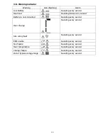
Page 25: ...Line mode ECO mode 40 70Hz 50Hz 60Hz Frequency Converter 4 Battery mode 10 Bypass mode Standby mode 13 Bus start fail 01 14 Bus over 02 27 Bus under 03 28 Bus unbalance 04 x 41 Inverter soft start fai...

Page 26: ...25 06 Bypass ENA DIS 07 HLS Bypass high LLS Bypass low 230 264 170 220 08 ENA DIS 09 0 999 0 999 00...

Page 27: ...26 01 208Vac 220Vac 230Vac 240Vac 02 CF ENA CF DIS 03 BAT 50 50Hz BAT 60 60Hz CF 50 50Hz CF 60 60Hz 04 ENA ECO DIS ECO 05 HLS LLS 24V 7V...

Page 28: ...27 4 10 ENA DIS ESC HLS LLS BAT CF EP EPO FA TP CH 3 1 8 1 2 3 4 5 6 7 8 1 2 3...

Page 29: ...28 H M S Vac Vdc Hz 0 25 26 50 51 75 76 100 4 Bypass 4 0 25 26 50 51 75 76 100 Vac Vdc Hz...

Page 30: ...29 ON Mute Button 2 5 OFF Enter Button 2 Select Button 10 5 5...

Page 31: ...30 Top Vision 24 03 9000 940 03 9000900 03 9027444 10 48091...

Reviews: