background image

Appendix F  BIOS Setting

5 9

F.2

PC Status Monitoring

The TPC-1560 is designed with status monitoring circuitry. In BIOS the
status could be shown. However, because the TPC-1560 is fan-less, it
could not activate any fan to cool down the CPU like ordinary PC
does.

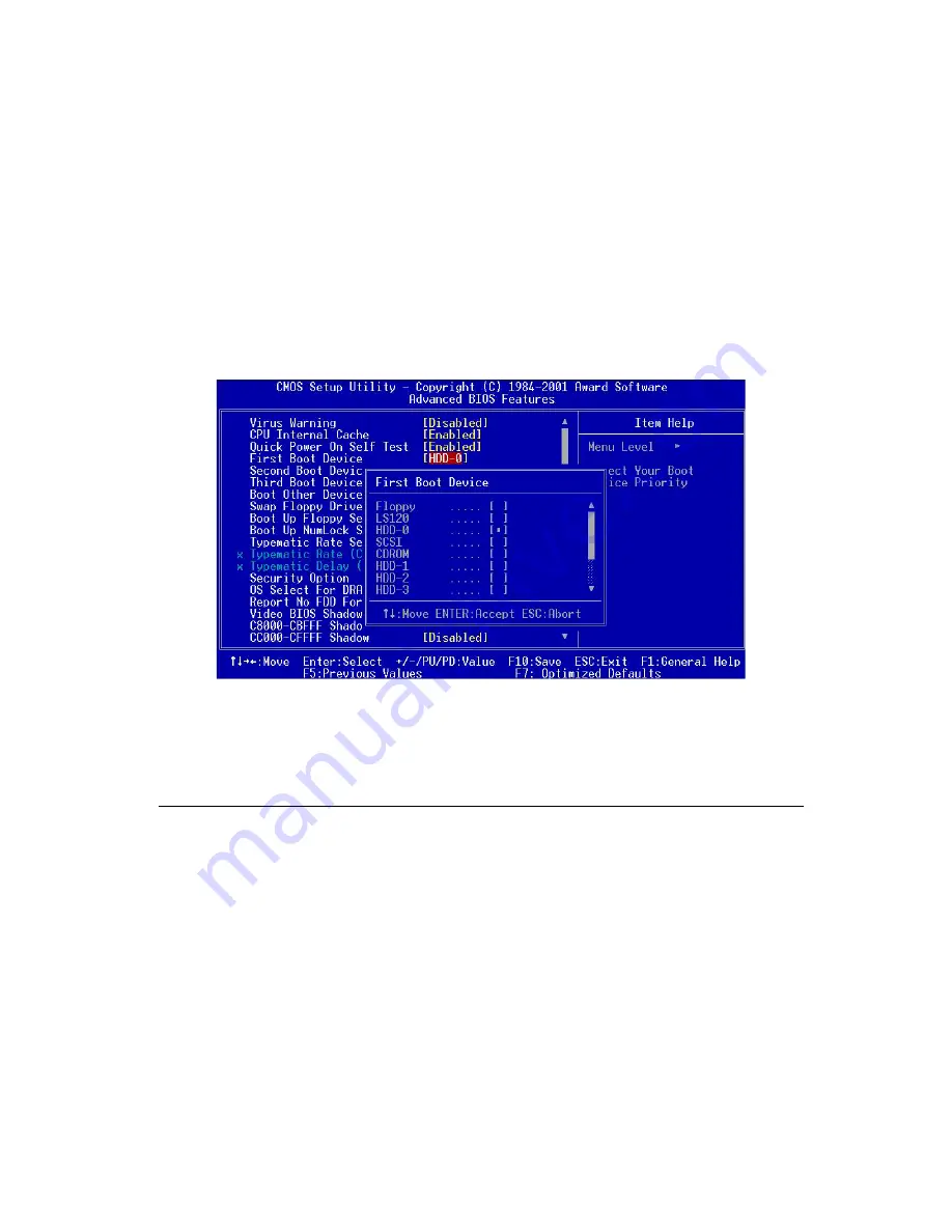
Note that there are options for boot devices including first, second,
third and even other boot devices. In TPC-1560 we have the defini-
tions as following:

HDD-0:

defined as the HDD module of the TPC-1560.

HDD-1:

defined as the CompactFlash.

CD-ROM: as external CD-ROM is connected via the CF-to-IDE adapter
board, "CD-ROM" must be chosen.

        Figure F-3: Selecting proper devices

Summary of Contents for TPC-1560

Page 1: ...TPC 1560 High performance operator interface terminal with 15 flat panel display User s Manual...

Page 2: ...rmation provided in this manual is intended to be accurate and reliable However Advantech Co Ltd assumes no responsibility for its use nor for any infringements upon the rights of third parties which...

Page 3: ...wer connector 7 TPC 1560 support CD 8 32MB CompactFlash memory card with Windows CE operating system 9 1 meter 9 pin to 9 pin null modem cable 10 Microsoft Windows CE end user license agreement 11 Y c...

Page 4: ...ce when the equipment is operated in a commercial environment This equipment generates uses and can radiate radio frequency energy If not installed and used in accordance with this user s manual it ma...

Page 5: ...ons and warnings on the equipment should be noted 11 If the equipment is not used for a long time disconnect it from the power source to avoid damage by transient over voltage 12 Never pour any liquid...

Page 6: ...t wird im Falle einer berspannung eine Besch digung vermieden 12 Durch die L ftungs ffnungen d rfen niemals Gegenst nde oder Fl ssigkeiten in das Ger t gelangen Dies k nnte einen Brand bzw elektrische...

Page 7: ...7 1 Panel mounting 7 1 7 2 Wall mounting desktop stand 8 1 8 Exploded diagram 9 1 9 Dimensions and cutout 10 Chapter 2 System Quick Starting 11 Chapter 3 The Engine of the TPC 1560 17 3 1 Introduction...

Page 8: ...ormat RS 422 Control Settings 37 A 3 COM3 Mode Selecting 37 Appendix B Watchdog Timer Programming 39 B 1 Watchdog timer programming example 40 Appendix C Windows 2000 Touch Screen Installation 41 C 1...

Page 9: ...Figure 3 3 1 TPC 1560 I O board 20 Figure 5 1 1 Adjust LCD contrast 28 Figure 5 1 2 Remove the CPU Board cover 28 Figure 5 1 3 Adjusting the LCD brightness 29 Figure 6 1 1 CPU board cover 32 Figure 6...

Page 10: ...1 LCD specifications 5 Table 1 2 1 Touchscreen specifications 6 Table 3 2 1 TPC 1560 main board connector jumper list 18 Table 3 2 2 J1 RTC control jumper 19 Table 3 3 1 TPC 1560 I O board connector...

Page 11: ...is chapter gives background information on the TPC 1560 Sections include Introduction Specifications LCD Specifications Touchscreen specifications Power I O ports Mounting Exploded diagram Dimensions...

Page 12: ...ay the high brightness TFT LCD display fits the industrial demand well Fan less and modular CPU board the introduction of low power processor prevents this system from unreliable fans In addition the...

Page 13: ...rnet controller IEEE 802 3u protocol compatible Watchdog timer MAX706 watchdog timer 1 6 second timeout period IDE 1 EIDE channel supports one 2 5 IDE HDD and one Compact Flash card simultaneously Flo...

Page 14: ...the HDD does not contain operating system the TPC 1560 will automatically boot from the CompactFlash 2 HDD exists only the system will boot from the HDD 3 CompactFlash card exists only the system wil...

Page 15: ...5 1 n o i t u l o s e R m u m i x a M A G X 8 6 7 x 4 2 0 1 s r o l o C m u m i x a M r o l o c e u r t n o i l l i m 7 7 6 1 m m H x W h c t i p l e x i P 7 9 2 0 x 7 9 2 0 e l g n a g n i w e i V 0...

Page 16: ...04 expansion slot The arrangement of these ports is shown in Figure 1 6 1 Table 1 4 1 Touchscreen specifications e p y T e v i t s i s e R n o i t c u r t s n o c s s a l g e s a B s s a l G d e r e p...

Page 17: ...Install the TPC 1560 to the panel opening 3 Find out the ten clampers and ten long screws in the accessory pack Hook those clampers to those holes around the four sides of the bezel Insert the screws...

Page 18: ...Wall mounting desktop stand There are two pairs of threaded holes on the sides of the front bezel They are used for wall mounting or desktop mounting Please contact with local Advantech sales represen...

Page 19: ...Chapter 1 General Information 9 Figure 1 8 1Exploded diagram 1 8 Exploded diagram...

Page 20: ...10 TPC 1560 User s Manual Figure 1 9 1 Dimensions and cutout 1 9 Dimensions and cutout Weight 3 8kg with one 2 5 HDD Dimension 383x307x55mm WxHxD Cutout 373 5 x 297 5 mm suggested...

Page 21: ...2 System Quick Starting This chapter provides a brief explanation for operating the TPC 1560 With these step by step guidelines it s easy to make the TPC 1560 start working C H A P T E R...

Page 22: ...5 HDD containing certain operating system and even application programs on the TPC 1560 Please refer to section 1 2 3 for the boot up sequence The Appendix E depicts the details to install hard disk...

Page 23: ...3 Install CompactFlash memory card Warning Though the CompactFlash memory card is supposed to be hot swappable it is suggested to turn off system power as plug in or pull out the card Thus the potenti...

Page 24: ...tor pin assignment Warning If the power lines are not connected to correct pins the system may be damaged as the power is turned on Step 4 Plug the power lines to the system power receptor Figure 2 6...

Page 25: ...Chapter 2 Quick Start Guide 15 Figure 2 7 Turn on power switch Step 6 Calibrate touchscreen The detailed procedure is described in section 5 2 Step 5 Turn on the system power switch...

Page 26: ...16 TPC 1560 User s Manual...

Page 27: ...3 The Engine of the TPC 1560 The operating engine of the TPC 1560 is composed of two PC boards the main boards and the I O boards C H A P T E R...

Page 28: ...tion feasible 3 2 CPC 2365 main board Table 3 2 1 TPC 1560 main board connector jumper list Figure 3 2 1 TPC 1560 main board l e b a L n o i t c n u F 2 N C n i P 4 4 1 M M I D O S r o t c e n n o c C...

Page 29: ...Chapter 3 The Engine of the TPC 1260 19 Table 3 2 2 J1 RTC control jumper 3 2 1 Connector pin assingments t r o h s 2 1 t l u a f e d n o y r e t t a b C T R t r o h s 3 2 S O I B r a e l C...

Page 30: ...20 TPC 1560 User s Manual 3 3 TPC 1560 I O board Figure 3 3 1 TPC 1560 I O board...

Page 31: ...1 1 N C r o t c e n n o c B S U 2 1 N C r o t c e n n o c e n o h p o r c i M 3 1 N C r o t c e n n o c t u o o i d u A 4 1 N C r o t c e n n o c N A L 5 1 N C n i P 5 2 r o t c e n n o c t r o p l e...

Page 32: ...22 TPC 1560 User s Manual...

Page 33: ...4 System Limitations In compact and highly integrated systems like the TPC 1560 there are several limitations to operate This chapter intends to unveil them to avoid confusing users C H A P T E R...

Page 34: ...ucial for embedded applications The TPC 1560 is designed to be compatible with IBM MicroDrive IBM offers MicroDrive in the form factor of PCMCIA by an additional adapter card Inserted into PCMCIA slot...

Page 35: ...turn off the power or reset the system at that time or data may be lost 4 3 Compatibility with IDE CD ROM Drives The TPC 1560 is designed to have no internal CD ROM drive since it is supposed to be in...

Page 36: ...l USB devices require drivers to operate normally They are not plug and play at all Furthermore so far there is not USB driver for DOS This implies that it is impossible to have FIRST TIME SETUP of Mi...

Page 37: ...5 System Tuning From time to time it is necessary to tune system settings from the defaults The most common ones are included in this chapter C H A P T E R...

Page 38: ...uning The display brightness of the TPC 1560 is designed to be adjustable Remove the screw on the CPU board cover Then slide the CPU board cover toward the PC 104 slot Take away the CPU board cover Fi...

Page 39: ...een drivers in the support CD The TPC 1560 touchscreen drivers support DOS Win dows 9x Windows NT Windows 2000 Windows Me Refer to Appen dix C for detailed setting on the Windows 2000 touchscreen driv...

Page 40: ...30 TPC 1560 User s Manual...

Page 41: ...6 Maintenance In practice users may need on site maintenance This chapter covers several simple repairings that can be done by qualified technicians C H A P T E R...

Page 42: ...e dedicated to describe how a qualified technician can replace major components 6 1 CPU board replacement Step 1 Remove the screw on the CPU board cover Step 2 Slide the CPU board cover toward the opp...

Page 43: ...U board would swing up Pull out the CPU board Figure 6 1 3 Remove the CPU board Step 7 Insert a new CPU board to the SO DIMM connector Step 8 Push down and lock the CPU board Step 9 Use a pair of twee...

Page 44: ...nt Step 1 Remove the fuse cover Step 2 Replace the damaged fuse with a new one Step 3 Replace the fuse cover Figure 6 2 1 Replace the fuse Warning 1 Do not replace the fuse unless it is damaged 2 Do n...

Page 45: ...A A P P E N D I X Serial Port Settings...

Page 46: ...n the two wired RS 485 communication is activated the TPC 1560 can automatically detect the data flow direction at this port Its setting are are selected by DIP switches SW1 SW2 and jumpers JP5 JP12 T...

Page 47: ...tings On Off Default A 3 COM3 Mode Selecting Beside the 24VDC power connector there is a small plastic lid fastened by a screw After removing the lid there appears a set of jumpers which allows select...

Page 48: ...38 TPC 1560 User s Manual...

Page 49: ...B A P P E N D I X Watchdog Timer Programming Example...

Page 50: ...ogram in assembly language gives hint to utilize the watchdog timer under operating systems such as DOS Windows 9x NT etc Step 1 activate the watchdog timer Step 2 clear the watchdog timer Step 3 re t...

Page 51: ...C A P P E N D I X Windows 2000 Touch Screen Installation...

Page 52: ...ouchscreen driver the system would restart automatically And the following fine tuning is required Step 1 Find out the touchscreen driver that is on the TPC 1560 support CD Execute the setup program I...

Page 53: ...Appendix C Windows 2000 43 Step 3 Click the Device Manager button Figure C 2 Device manager...

Page 54: ...ce and other pointing devices there is a exclamation mark appearing at the beginning of the line of touchscreen Move the cursor to this line TouchScreen PS 2 Mouse R411 PS2 and press right button of t...

Page 55: ...Appendix C Windows 2000 45 Step 5 Then move the cursor to the Microsoft PS 2 mouse or Other PS 2 compatible mouse press the right button of the mouse Select Properties Figure C 4 Mouse properties...

Page 56: ...46 TPC 1260 User s Manual Step 6 Go to the Driver page and click the Update Driver button Figure C 5 Update driver...

Page 57: ...Appendix C Windows 2000 47 Step 7 Click Next button Choose the Display a list of the known drivers for this device radial button Click Next button Figure C 6 Select driver from known list...

Page 58: ...48 TPC 1260 User s Manual Step 8 In the Manufacturers list find out and select Touch Screen Figure C 7 Find out TouchScreen in the manufacturers list...

Page 59: ...Appendix C Windows 2000 49 Step 9 Click the Next button to install driver Ignore the warning message appears Figure C 8 Re install the driver...

Page 60: ...TPC 1260 User s Manual Step 10 When the installation finishes the system would restart Thus complete the setup of the touchscreen under Windows 2000 Figure C 9 Finish installation of touchscreen driv...

Page 61: ...D A P P E N D I X Fuse Specifications...

Page 62: ...52 TPC 1260 User s Manual D Fuse Specifications The fuse used on the TPC 1560 is Rating 250VAC 5Amp Size 5x20mm Notice The fuse is set to break as the input voltage exceeds 33 VDC for your protection...

Page 63: ...E A P P E N D I X HDD Module Assembling Dismounting Guide...

Page 64: ...e following items are included in the TPC 1560T module 1 Rubber feet screws x 4 M3 x 4L nickel coating 2 Bracket screws x 4 M3 x 5L Nylok 3 Interface board screws x 2 M2 5 x 5L Nylok 4 Rubber feet x 4...

Page 65: ...e Assembling Dismounting Guide 55 2 Assembling HDD Step 1 Take the 2 5 IDE HDD to be assembled Cover the HDD insulator on its PCBA side Step 2 Squeeze the four rubber foot screws into the rubber feet...

Page 66: ...56 TPC 1260 User s Manual Step 3 Fasten these 4 rubber feet to the HDD insulator Step 4 Connect the IDE adapter cable...

Page 67: ...ndix E HDD Module Assembling Dismounting Guide 57 Step 5 Mate the HDD bracket to the HDD so that the four rubber feet are in positions Note that the direction to mate the bracket in the following figu...

Page 68: ...tep 7 Look at the IDE adapter board and the plastic case There is a reinforcement plate on the IDE adapter board and a reinforcement slot on the plastic case Step 6 Assemble the plastic from the oppos...

Page 69: ...unting Guide 59 Step 8 Insert the reinforcement plate into the reinforcement slot and align their screw holes Step 9 Fasten the plate and slot by interface board screws Step 10 Fasten the HDD bracket...

Page 70: ...the right then the lock is released Slide the whole HDD module into the opening on the TPC 1560 Note that the insulator i e the PCBA side should be toward users As the HDD module dock on position move...

Page 71: ...ne of the two 40 pin connectors of the IDE cable Note the CD ROM requires external power input This could be done by a normal PC switching power supply Step 5 Turn on the power of the system Step 6 If...

Page 72: ...62 TPC 1260 User s Manual...

Page 73: ...F A P P E N D I X BIOS Setting...

Page 74: ...F 1 Boot Devices The TPC 1560 accepts several kinds of devices as booting media As turning on the TPC 1560 enter the BIOS setting utility Choose Advanced BIOS Features Figure F 1 BIOS setting utility...

Page 75: ...fan to cool down the CPU like ordinary PC does Note that there are options for boot devices including first second third and even other boot devices In TPC 1560 we have the defini tions as following...

Page 76: ...60 TPC 1260 User s Manual...

Reviews: