


PCM-9577 User’s Manual
24
2.23 USB connectors (CN1, CN2)
The PCM-9577 board provides up to four USB (Universal Serial Bus)
ports which support USB 1.1 (PCM-9577F) or USB 2.0 (PCM-9577FG).
This gives complete Plug and Play, and hot attach/detach for up to 127
external devices. The USB interfaces comply with USB specification
Rev. 1.1, and are fuse protected.
The USB interface is accessed through two 5 x 2-pin flat-cable connec-
tors, CN1 (USB1, 2); and CN2 (USB3, 4) in the PCM-9577F model. The
PCM-9577FG Support Embedded USB interface in PCM-9577FG
model which used one 9 x 2-pin header connector for USB 3, 4 and one 5
x 2 pin header connector for USB 1, 2. You will need an adapter cable if
you use a standard USB connector. The adapter cable has a 5 x 2-pin con-
nector on one end and a USB connector on the other.
The USB interfaces can be disabled in the system BIOS setup.
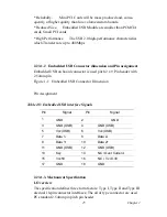
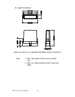
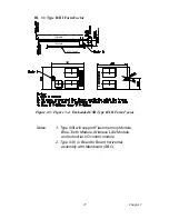
2.23.1 Embedded USB interface:
Overview
The Embedded USB interface Specification defines an alternate imple-
mentation for small form factor USB Module referred to in this specifica-
tion as a Embedded USB Module
This specification uses a qualified sub-set of the same signal protocol,
electrical definitions, and configuration definitions as the USB 2.0 Speci-
fication.
The primary differences between a standard USB 2.0 and a Embedded
USB Interface are:
*
Support more one Vcc +5V signal in the Embedded USB Interface
*
Support Vcc 3.3V and OVER CURRENT signal in the Embedded
USB Interface
2.23.1.1 Features and Benefits
*Upgrade ability. Embedded USB Module are removable and upgrade-
able with available“new technology” cards.
* Flexibility. A single Mini PCI interface can accommodate various
types of communications, Flash memory storage, and Industry control I/
O devices.
* Serviceability. Mini PCI Cards can be removed and easily serviced if
they fail.
Summary of Contents for PCM-9577
Page 10: ...PCM 9577 User s Manual x...
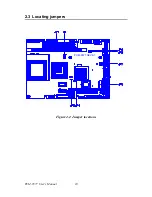
Page 20: ...PCM 9577 User s Manual 10 2 3 Locating jumpers Figure 2 1 Jumper locations PCM 9577 REV A1...
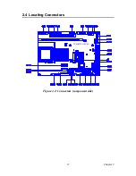
Page 21: ...11 Chapter2 2 4 Locating Connectors Figure 2 2 Connectors component side PCM 9577 REV A1...
Page 38: ...PCM 9577 User s Manual 28...
Page 44: ...PCM 9577 User s Manual 34...
Page 61: ...51 Chapter5 2 Choose the Adapter tab then press the Change button 3 Press the Have Disk button...
Page 65: ...55 Chapter5 2 Select Adapter then Change...
Page 66: ...PCM 9577 User s Manual 56 3 Press Next then Display a list 4 Press the Have disk button...
Page 70: ...PCM 9577 User s Manual 60 2 Choose the Settings tab and press the Display Type button...
Page 71: ...61 Chapter5 3 Press the Change button...
Page 75: ...65 Chapter5 2 Choose the Video Controller VGA Compatible button...
Page 76: ...PCM 9577 User s Manual 66 3 Choose the Drive button press Update Driver button...
Page 80: ...PCM 9577 User s Manual 70 2 Choose Hardware and Device Manager press OK button...
Page 81: ...71 Chapter5 3 Choose Video Controller VGA Compatible press OK button...
Page 86: ...PCM 9577 User s Manual 76...
Page 103: ...93 Chapter6 8 Press Next button 9 Press Finish to reboot...
Page 104: ...PCM 9577 User s Manual 94...
Page 110: ...PCM 9577 User s Manual 100 7 2 3 Installation for Windows 2000 1 Open Device Manager...
Page 111: ...101 Chapter7 2...
Page 112: ...PCM 9577 User s Manual 102 3 4...
Page 113: ...103 Chapter7 5 6...
Page 114: ...PCM 9577 User s Manual 104 7 8...
Page 116: ...PCM 9577 User s Manual 106 2 a Choose type of network b Click Next 3 a Click Select from list...
Page 118: ...PCM 9577 User s Manual 108 6 Check the highlighted item and click OK...
Page 119: ...109 Chapter7 7 Click Next to continue setup 8 Choose the networking protocols then click Next...
Page 122: ...PCM 9577 User s Manual 112...
Page 126: ...PCM 9577 User s Manual 116...
Page 129: ...119 AppendixB Figure B 1 PC 104 module mounting diagram...
Page 130: ...PCM 9577 User s Manual 120 Figure B 2 PC 104 module dimensions mm 0 1...
Page 156: ...PCM 9577 User s Manual 146...
Page 161: ...Appendix E Optional Extras for the PCM 9577...
Page 165: ...Appendix F Mechanical Drawings...
Page 167: ...157 AppendixF Figure F 2 PCM 9577 Mechanical Drawing solder side PCM 9577 REV A1...
Page 168: ...PCM 9577 User s Manual 158...


