


PCM-9577 User’s Manual
22
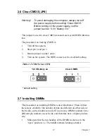
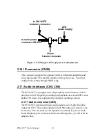
2.20 TV-out interface (optional) (CN20)
The PCM-9577 board provides optional TV-out via CN20. This consists
of a 5-pin wafer box header. Output supports composite video and S-
video connectors via an optional cable kit (p/n: 1103050306). TV-out
generators use both NTSC and PAL formats.
To set up your video interface:
1.
Run the appropriate installation program located on the utility disk.
That’s all there is to it.
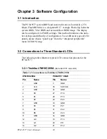
2.21 Ethernet configuration
The PCM-9577 is equipped with a high performance 32-bit PCI-bus
Ethernet interface which is fully compliant with IEEE 802.3U 10/
100Mbps CSMA/CD standards. It is supported by all major network
operating systems.
The medium type can be configured via the RSET8139.EXE program
included on the utility disk. (See Chapter 3 for detailed information.)
2.21.1 100Base-T connector (CN3, PCM-9577F)
10/100Base-T connects to the PCM-9577F via an adapter cable to a 10-
pin polarized header (CN3).
2.21.2 1000Base-T connector (CN8, PCM-9577FG)
10/100/1000 Base-T connects to the PCM-9577FG via an adapter cable
to a 10-pin polarized header (CN8).
2.21.3 Network boot
The Network Boot feature can be utilized by incorporating the Boot
ROM image files for the appropriate network operating system. The Boot
ROM BIOS files are included in the system BIOS, which is on the utility
CD disc.
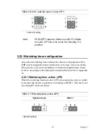
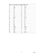
2.21.4 LAN controller power select (JP7)
Table 2.6: LAN controller power select (JP7)
5 V*
Standby 5V
Summary of Contents for PCM-9577
Page 10: ...PCM 9577 User s Manual x...
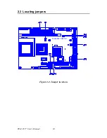
Page 20: ...PCM 9577 User s Manual 10 2 3 Locating jumpers Figure 2 1 Jumper locations PCM 9577 REV A1...
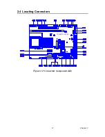
Page 21: ...11 Chapter2 2 4 Locating Connectors Figure 2 2 Connectors component side PCM 9577 REV A1...
Page 38: ...PCM 9577 User s Manual 28...
Page 44: ...PCM 9577 User s Manual 34...
Page 61: ...51 Chapter5 2 Choose the Adapter tab then press the Change button 3 Press the Have Disk button...
Page 65: ...55 Chapter5 2 Select Adapter then Change...
Page 66: ...PCM 9577 User s Manual 56 3 Press Next then Display a list 4 Press the Have disk button...
Page 70: ...PCM 9577 User s Manual 60 2 Choose the Settings tab and press the Display Type button...
Page 71: ...61 Chapter5 3 Press the Change button...
Page 75: ...65 Chapter5 2 Choose the Video Controller VGA Compatible button...
Page 76: ...PCM 9577 User s Manual 66 3 Choose the Drive button press Update Driver button...
Page 80: ...PCM 9577 User s Manual 70 2 Choose Hardware and Device Manager press OK button...
Page 81: ...71 Chapter5 3 Choose Video Controller VGA Compatible press OK button...
Page 86: ...PCM 9577 User s Manual 76...
Page 103: ...93 Chapter6 8 Press Next button 9 Press Finish to reboot...
Page 104: ...PCM 9577 User s Manual 94...
Page 110: ...PCM 9577 User s Manual 100 7 2 3 Installation for Windows 2000 1 Open Device Manager...
Page 111: ...101 Chapter7 2...
Page 112: ...PCM 9577 User s Manual 102 3 4...
Page 113: ...103 Chapter7 5 6...
Page 114: ...PCM 9577 User s Manual 104 7 8...
Page 116: ...PCM 9577 User s Manual 106 2 a Choose type of network b Click Next 3 a Click Select from list...
Page 118: ...PCM 9577 User s Manual 108 6 Check the highlighted item and click OK...
Page 119: ...109 Chapter7 7 Click Next to continue setup 8 Choose the networking protocols then click Next...
Page 122: ...PCM 9577 User s Manual 112...
Page 126: ...PCM 9577 User s Manual 116...
Page 129: ...119 AppendixB Figure B 1 PC 104 module mounting diagram...
Page 130: ...PCM 9577 User s Manual 120 Figure B 2 PC 104 module dimensions mm 0 1...
Page 156: ...PCM 9577 User s Manual 146...
Page 161: ...Appendix E Optional Extras for the PCM 9577...
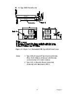
Page 165: ...Appendix F Mechanical Drawings...
Page 167: ...157 AppendixF Figure F 2 PCM 9577 Mechanical Drawing solder side PCM 9577 REV A1...
Page 168: ...PCM 9577 User s Manual 158...