APPENDIX C
PCI-1711/1731 User’s Manual
Advantech Co., Ltd.
www.advantech.com
– 42 –
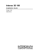
Read
Channel Number and A/D Data
Bit #
7
6
5
4
3
2
1
0
BASE+1
CH3
CH2
CH1
CH0
AD11 AD10
AD9
AD8
BASE+0
AD7
AD6
AD5
AD4
AD3
AD2
AD1
AD0
C.3 Channel Number and A/D Data — BASE+0 and
BASE+1
BASE+0 and BASE+1 hold the result of A/D conversion data.
The 12 bits of data from the A/D conversion are stored in BASE+1 bit
3 to bit 0 and BASE+0 bit 7 to bit 0.BASE+1 bit 7 to bit 4 hold the
source A/D channel number.
Table C-2 Register for channel number and A/D data
AD11 ~ AD0
Result of A/D Conversion
AD0 the least significant bit (LSB) of A/D data
AD11 the most significant bit (MSB)
CH3 ~ CH0
A/D Channel Number
CH3 ~ CH0 hold the number of the A/D channel
from which the data is received
CH3: MSB
CH0 :LSB
C.4 Software A/D Trigger — BASE+0
You can trigger an A/D conversion by software, the card's on-board
pacer or an external pulse.
BASE+6, Bit 2 to bit 0, select the trigger source.
(see Section C.7, Control Register -- BASE+6 )
If you select software triggering, a write to the register BASE+0 with
any value will trigger an A/D conversion.