ITA-2000 User Manual
/ 用户手册
58
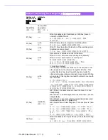
Table A.1: Watchdog Timer Registers
/ 看门狗定时器寄存器
Address of
Register (2E)
寄存器 (2E)
地址
Attribute
属性
Read/Write
读取 / 写入
Value (2F) &
description
数值 (2F) &
说明
87 (hex)
-----
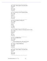
Write this address to I/O address port 2E (hex) twice to
unlock the W83627DHG.
向 I/O 地址端口 2E (hex)写入该地址两次,解锁
W83627DHG。
07 (hex)
write
写入
Write 08 (hex) to select register of watchdog timer.
写入 08 (hex)选择看门狗定时器寄存器。
30 (hex)
write
写入
Write 01 (hex) to enable the function of the watchdog timer.
Disabled is set as default.
写入 01 (hex)启用看门狗定时器功能。默认为禁用。
F5 (hex)
write
写入
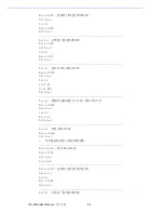
Set seconds or minutes as units for the timer.
Write 0 to bit 3: set second as counting unit. [default]
Write 1 to bit 3: set minutes as counting unit.
将定时器计时单位设置为秒或分钟:
向 bit 3 写入 0:将计时单位设置为秒。(默认)
向 bit 3 写入 1:将计时单位设置为分钟。
F6 (hex)
write
写入
0: stop timer [default]
01~FF (hex): The amount of the count, in seconds or min-
utes, depends on the value set in register F5 (hex). This
number decides how long the watchdog timer waits for
strobe before generating an interrupt or reset signal. Writing
a new value to this register can reset the timer to count with
the new value.
0:停止定时器 ( 默认 )。
01
~
FF (hex):计时值,单位为秒或分钟,取决于寄存器 F5
(hex)的设置值。该值说明了看门狗定时器等待选通的时间
达到何值时产生中断或复位信号。向该寄存器写入新值可以
复位定时器,使其以新值开始计时。
F7 (hex)
read/write
读取 / 写入
Bit 7:Write 1 to enable mouse to reset the timer, 0 to dis-
able[default].
Bit 6: Write 1 to enable keyboard to reset the timer, 0 to dis-
able.[default]
Bit 5: Write 1 to generate a timeout signal immediately and
automatically return to 0. [default=0]
Bit 4: Read status of watchdog timer, 1 means timer is “time-
out”.
Bit 7:写入 1 启用鼠标复位定时器,写入 0 禁用 (默认)。
Bit 6:写入 1 启用键盘复位定时器,写入 0 禁用 (默认)。
Bit 5:写入 1 立即产生超时信号,并自动返回到 0 (默认
为 0)。
Bit 4:读取看门狗定时器状态,1 表示定时器 “超时”。
AA (hex)
-----
Write this address to I/O port 2E (hex) to lock the watchdog
timer 2.
向 I/O 端口 2E (hex)写入该地址,锁定看门狗定时器 2。
Summary of Contents for ITA-2000
Page 8: ...ITA 2000 User Manual viii...
Page 12: ...ITA 2000 User Manual xii...
Page 16: ...ITA 2000 User Manual 4 1 5 Dimension Diagram Figure 1 1 Dimension diagram...
Page 28: ...ITA 2000 User Manual 16...
Page 29: ...Chapter 3 3 BIOS Operation BIOS This chapter describes how to set BIOS configuration data BIOS...
Page 60: ...ITA 2000 User Manual 48...
Page 61: ...Chapter 5 5 System Setup This chapter introduces the instal lation process...
Page 67: ...Appendix A A Programming the Watchdog Timer...
Page 79: ...Appendix B B Examples of the CAN Transfer tool CAN...


